Diagnosing Automotive Faults with Class D Audio Amplifiers(7)
Tweeter Detection
This diagnostic detects whether a tweeter is properly connected when a passive crossover is used. To detect shorted loads, place the device in normal mode; set the CTRL3.TW (tweeter/shorted load diagnostic select) bit to 1; set MAP.LCTM to 1; and apply a 15kHz to 25Hz sinusoidal signal to all the inputs. The device compares the load current to the tweeter-detect current threshold. If the load current exceeds the threshold, the corresponding STAT3./LOAD_ (load indicator) bit is set to 1, indicating that there is a tweeter. The amplitude of the input signal depends on the impedance versus frequency characteristics of the tweeter. Correct tweeter detection requires that the amplitude be large enough to trip the threshold when a tweeter is present.
Note that the active-low LOAD_ bits do not latch high upon detecting a tweeter. During zero crossings, the load current does not exceed the threshold and the active-low LOAD_ bits are cleared to 0. There are two ways to obtain the results of the tweeter detection diagnostic:
- Continuously read the active-low LOAD_ bits to determine if any have been set high.
- Monitor the open-drain active-low CL0 output. Because active-low CLP0 is the NORed function of the active-low LOAD_ bits, active-low CLP0 pulls low if a short exists on any of the outputs.
Mask the active-low LOAD_ bits to the active-low CL0 output by setting the MAP.LCTM (tweeter and shorted load mask) bit to 1 when the tweeter detection diagnostic is no longer running. Doing this prevents active-low CL0 from being asserted when the tweeter-detect current threshold is breached during play.
The tweeter detection diagnostic is done on all outputs. The presence of a tweeter is traceable to any output by examining the active-low LOAD_ bits. The presence of a tweeter on output 3 causes active-low LOAD3 to go high, etc.
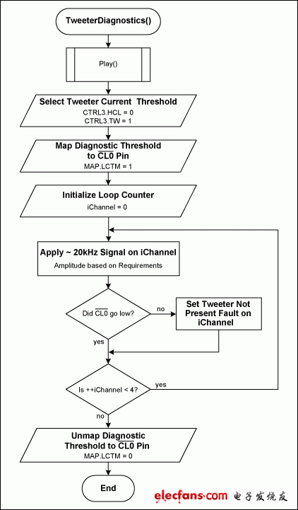
Step-by-Step Procedure (Figure 9)
- Set CTRL3.HCL = 0.
- Map the diagnostic current threshold to the active-low CL0 pin by setting MAP.LCTM = 1.
- Enter PLAY mode by following the normal startup procedure.
- Set the diagnostic current threshold to low by setting CTRL3.TW = 1.
-
For each output [0 to 3]:
- Generate a high-frequency sine wave (15kHz to 25kHz) with an amplitude based on application requirements. You must check one output at a time to determine which output has an open tweeter.
- Monitor active-low CL0 or read OSTAT1.LOAD[3:0] to determine whether the current threshold is crossed. This status is not latched, so it will toggle on/off based on the signal amplitude.
- Remove the diagnostic current-threshold mapping by setting MAP.LCTM = 0.
- Select the normal diagnostic current threshold by setting CTRL3.TW = 0.
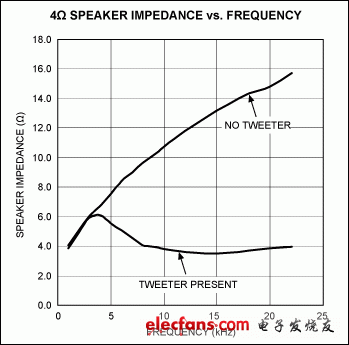
To select the optimum input-voltage amplitude, measure the speaker impedance with and without a tweeter present at the test frequency selected. Below is a typical 4Ω speaker impedance curve with and without the tweeter present.

Figure 8. Typical 4Ω speaker impedance vs. frequency.
With a test frequency of 20kHz the optimum input voltage is where the active-low CL0 pin asserts with a speaker impedance of:
Where:
RTW = Speaker impedance with tweeter presen
RNO-TW = Speaker impedance with no tweeter
Using the equation above and the data in Figure 8:

Figure 9. Tweeter diagnostic procedure.
- 第 1 页:Diagnosing Automotive Faults with Class D Audio Amplifiers(1)
- 第 2 页:Three-State Procedure#
- 第 3 页:Load Diagnostics#
- 第 4 页:Short-to-Ground Diagnostic Procedure#
- 第 5 页:Open Load Detection#
- 第 6 页:Shorted Load/Resistance Measurement Detection#
- 第 7 页:Tweeter Detection#
- 第 8 页:Continuous Diagnostics#
本文导航
非常好我支持^.^
(0) 0%
不好我反对
(0) 0%
相关阅读:
- [新品快讯] 新唐科技推出emPowerAudio系列ISD810X音频功放 2011-03-22
- [电子动态] Wolfson推出高传真音讯(HD Audio)新产品线 为PC和NB掀 2011-01-27
- [厂商新闻] 欧胜面向电脑和笔记本电脑推出高清晰度音频( 2011-01-09
- [新品快讯] 欧胜微电子推出WM8958音频中心(Audio Hub)解决 2010-11-08
- [模拟威廉希尔官方网站 ] High-efficiency Class D audio 2010-09-22
- [LED电路] 9个LED组成的音频电平表电路, Audio VU mete 2010-03-28
- [模拟威廉希尔官方网站 ] TV audio amplifiers—thermal te 2010-03-03
- [新品快讯] ADI推出Audio Processor全系列提供多组的DA 2010-01-25
( 发表人:爱电路 )


