Diagnosing Automotive Faults with Class D Audio Amplifiers(6)
Shorted Load/Resistance Measurement Detection
This diagnostic can measure the resistance of the load so that shorted loads on any of the outputs can be detected. Since a resistance can be calculated from the diagnostic, this diagnostic can also be used as an alternate method to detect open load or to determine if the speaker is present. To detect shorted loads, place the device in normal mode; set the CTRL3.TW (tweeter/shorted load diagnostic select) bit to 0; set MAP.LCTM to 1 to map the active-low LOAD_ fault bits to the active-low CL0 pin; and apply a ≤ 20Hz sinusoidal signal or single half-sine signal pulse to the inputs under test. The amplitude of the signal will depend on application requirements. The device compares the load current to the shorted load-current threshold. If the load current exceeds the threshold, the corresponding STAT3./LOAD_ (load indicator) bit is set to 1, indicating that there is a shorted load. The shorted load-current threshold depends on the programmed current limit. (See the Electrical Characteristics table in the data sheet.) A similar procedure can be used to detect an open load by using a larger amplitude sinusoidal signal.
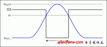
Note that the active-low LOAD_ bits do not latch high upon detecting a short. During zero crossings, the load current does not exceed the threshold and the active-low LOAD bits are cleared to 0. There are two ways to obtain the results of the shorted-load diagnostic:
- Continuously read the active-low LOAD_ bits to determine if any have been set high.
- Monitor the open-drain active-low CL0 output. Because active-low CL0 is the NORed function of the active-low LOAD bits, active-low CL0 pulls low if a short exists on any of the outputs.
Mask the active-low LOAD_ bits to the active-low CL0 output by setting the MAP.LCTM (tweeter and shorted load mask) bit to 0 when the shorted-load diagnostic is not longer running. Clearing this bit prevents active-low CL0 from being asserted when the shorted load-current threshold is exceeded during play.
A load-resistance-measurement diagnostic is done on all outputs. A shorted load is traceable to the output on which it exists by examining the active-low LOAD_ bits or injecting the sinusoidal signal into one channel at a time.
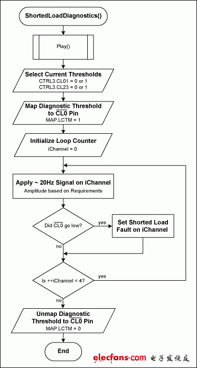
Step-by-Step Procedure (Figure 7)
- Enter PLAY mode by following the normal startup procedure.
- Select the low-current threshold by setting CTRL3.HCL = 0. This current is approximately 1.3A. (See the Electrical Characteristics table in the data sheet.)
- Map the diagnostic current threshold to the active-low CL0 pin by setting MAP.LCTM = 1.
- Set the current threshold to a high setting for short detection by setting CTRL3.TW = 0. If you are running an open test, set CTRL3.TW = 1 to select the lower current threshold setting.
-
For each output [0 to 3]:
- Generate a low-frequency sine wave (typically ≤ 20Hz) or single-pulse half-sine wave with the amplitude based on application requirements. If the amplitude of the sine wave is ramped until active-low CL0 is active, then the exact speaker impedance can be measured.
- Monitor active-low CL0 or read OSTAT1.LOAD[3:0] to determine whether the current threshold is crossed. This status is not latched, so it will toggle on/off based on the signal amplitude. If monitoring active-low CL0, you must apply the input signal to one channel at a time. You can also read the active-low LOAD status bits through the I²C to determine which output caused the active-low CL0 pin to assert.
- Remove the diagnostic current threshold mapping by setting MAP.LCTM = 0.
There are several ways to measure the exact resistance of the load:
-
Ramp up the sine wave or half-sine pulses slowly until the active-low CL0 pin is asserted for the first time. The resistance is then calculated by:
Where:
IT = Threshold current set by CTRL3.HCL
VINP = Peak input voltage signal
GAIN = Gain setting of the channel
-
Use a sine wave or a single half-sine pulse with an amplitude guaranteed to trip the selected threshold current with expected load resistance. When the test signal is applied, measure the amount of time that active-low CL0 is low. From this the load resistance can be calculated as follows:


Figure 7. Shorted-load diagnostic procedure.
- 第 1 页:Diagnosing Automotive Faults with Class D Audio Amplifiers(1)
- 第 2 页:Three-State Procedure#
- 第 3 页:Load Diagnostics#
- 第 4 页:Short-to-Ground Diagnostic Procedure#
- 第 5 页:Open Load Detection#
- 第 6 页:Shorted Load/Resistance Measurement Detection#
- 第 7 页:Tweeter Detection#
- 第 8 页:Continuous Diagnostics#
本文导航
非常好我支持^.^
(0) 0%
不好我反对
(0) 0%
相关阅读:
- [新品快讯] 新唐科技推出emPowerAudio系列ISD810X音频功放 2011-03-22
- [电子动态] Wolfson推出高传真音讯(HD Audio)新产品线 为PC和NB掀 2011-01-27
- [厂商新闻] 欧胜面向电脑和笔记本电脑推出高清晰度音频( 2011-01-09
- [新品快讯] 欧胜微电子推出WM8958音频中心(Audio Hub)解决 2010-11-08
- [模拟威廉希尔官方网站 ] High-efficiency Class D audio 2010-09-22
- [LED电路] 9个LED组成的音频电平表电路, Audio VU mete 2010-03-28
- [模拟威廉希尔官方网站 ] TV audio amplifiers—thermal te 2010-03-03
- [新品快讯] ADI推出Audio Processor全系列提供多组的DA 2010-01-25
( 发表人:爱电路 )
