 电子发烧友App


 创作
创作 发文章
发文章 发帖
发帖  提问
提问  发资料
发资料 发视频
发视频资料介绍
描述
在本主题中,我们将讨论如何开始使用 Arduino 和 SD 卡(microSD 卡)的简单 proteus interwetten与威廉的赔率体系 。
我将在本主题的后面部分解释如何阅读有关 SD 卡的信息,以使您熟悉该概念。在本例中,我们将学习如何使用winimage软件创建映像文件,并使用winimage和SD 库选择某些参数,如卷类型、可用空间和其他信息,并通过串行端口发送。然后我们将模仿 proteus 中的示例,以达到类似于实际实验的最佳所需结果。
Arduino 的 SD 卡库非常出色,它使与 SD 卡的交互非常简单。使用 Arduino SD 库可以读取和写入 SD 卡。它基于 William Greiman 的 sdfatlib。在普通 SD 和 SDHC 卡上,该库支持 FAT16 和 FAT32 文件系统。对于文件名,它使用 8.3 短名称。
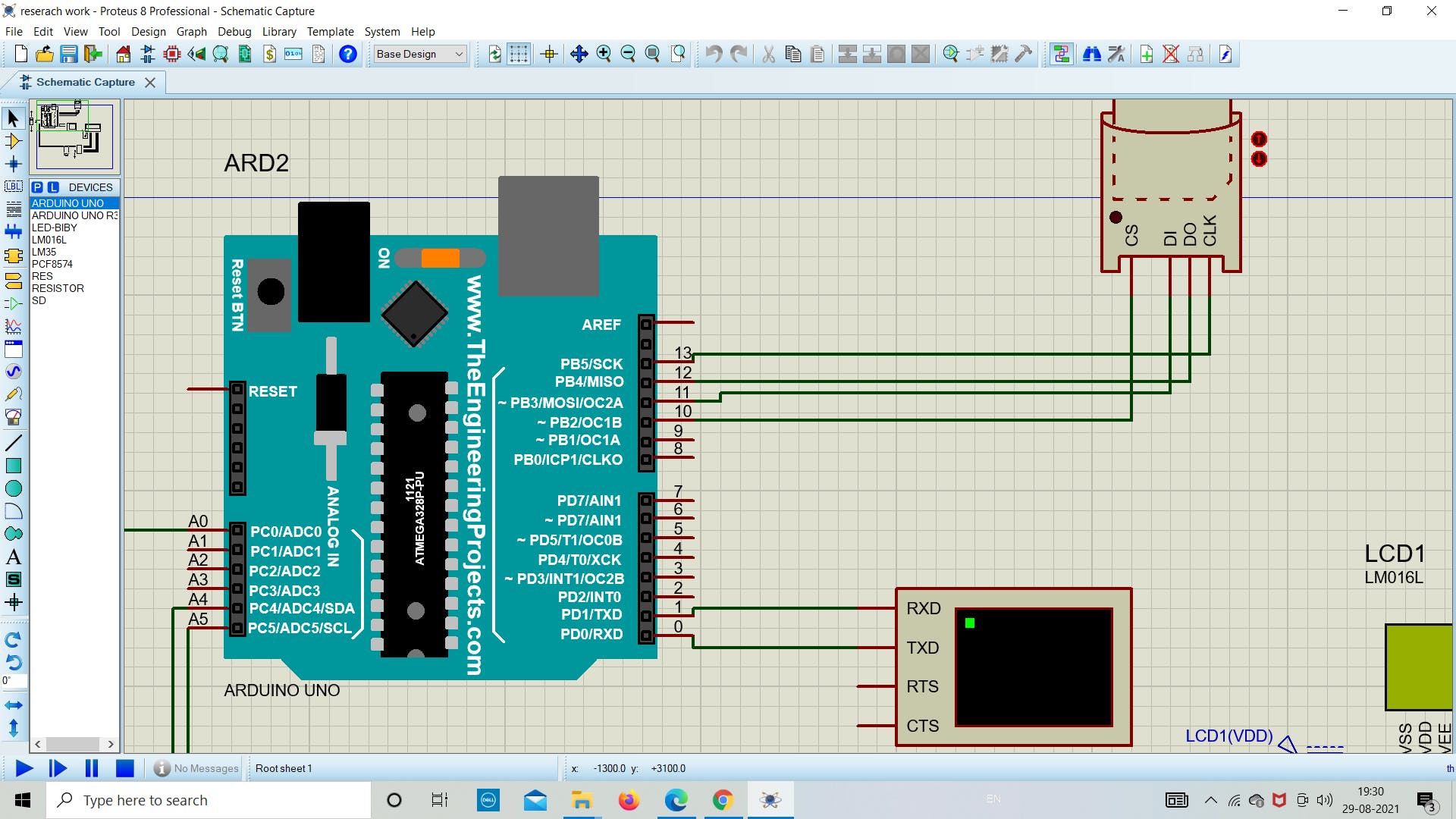
SPI 用于在微控制器和 SD 卡之间进行通信,它位于数字引脚 11、12 和 13(在大多数 Arduino 板上)或 50、51 和 52(在某些 Arduino 板上)(Arduino Mega)。还需要第二个引脚来选择 SD 卡。可以使用硬件 SS 引脚(大多数 Arduino 板上的引脚 10 或 Mega 上的引脚 53)或 SD.begin() 调用中指定的另一个引脚。
所需组件
硬件
- Arduino板
- 具有 FAT16 或 FAT32 文件系统的 SD 卡
- LM35
- 虚拟终端(作为串行监视器)
- PCF8574 I2C液晶接口模块
- LM016L (LCD) 显示器
- R1 & R2 = 10k 欧姆
软件
- 变形虫
- Arduino IDE
- Winimage
1.先决条件练习
在我们开始进行实际零件仿真之前,我们将通过简单的下载、安装和设置 Arduino IDE 和 Proteus 库的练习来热身。
一世。安装 Winimage
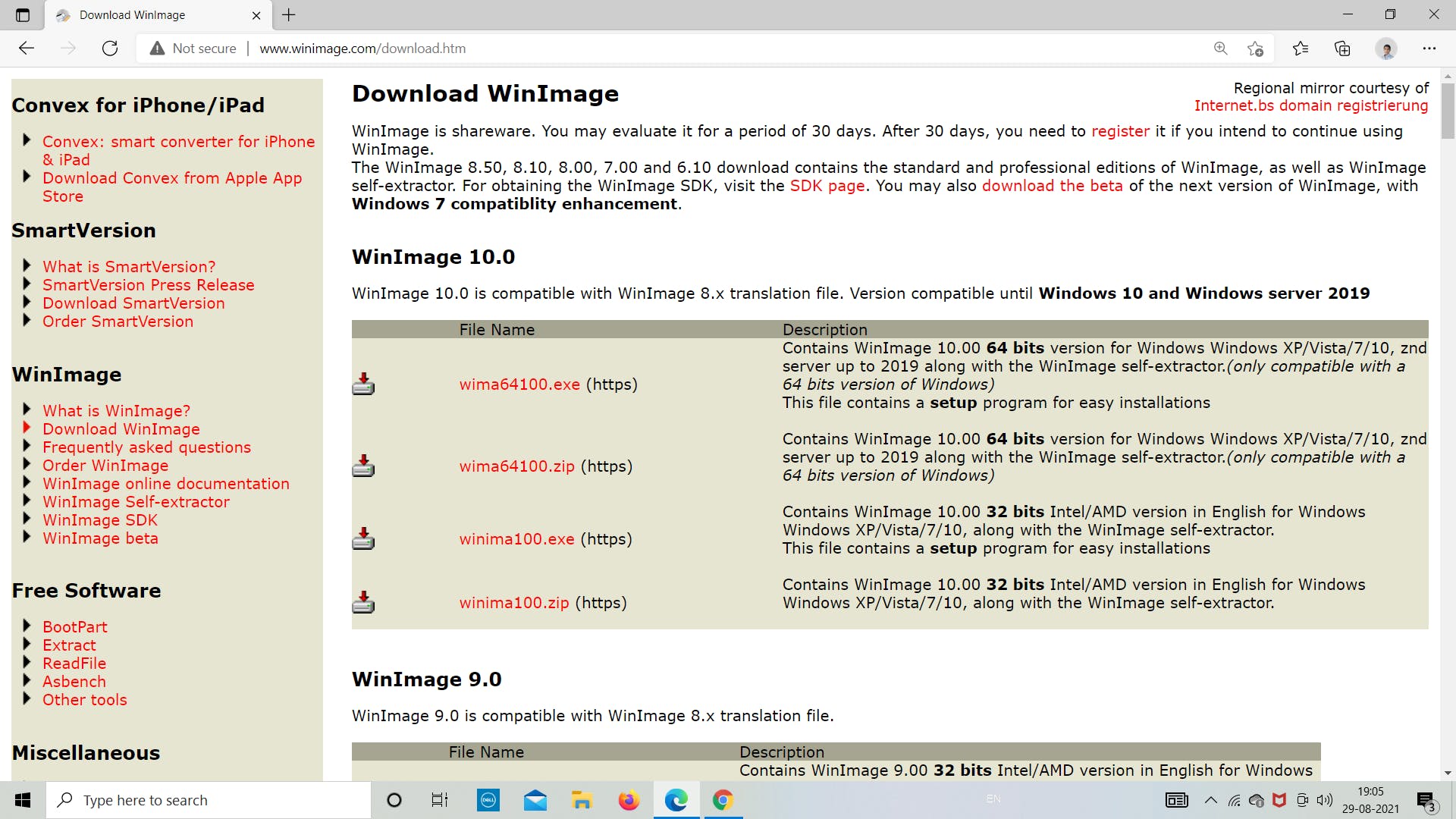
我们的第一步是从 Internet 下载 winimage 并将下载路径设置为便于以后访问。根据系统要求,从官网选择相应的 latest.exe 文件。
一世。在 IDE 中添加 SD 卡库
现在我们将从 IDE 下载 SD 库。请按照下图所示的步骤了解有关如何下载适用于 Arduino IDE 的 SD 库的更多信息。我们将使用这个库来为 Arduino 编程 SD 卡模块以存储和检索数据。
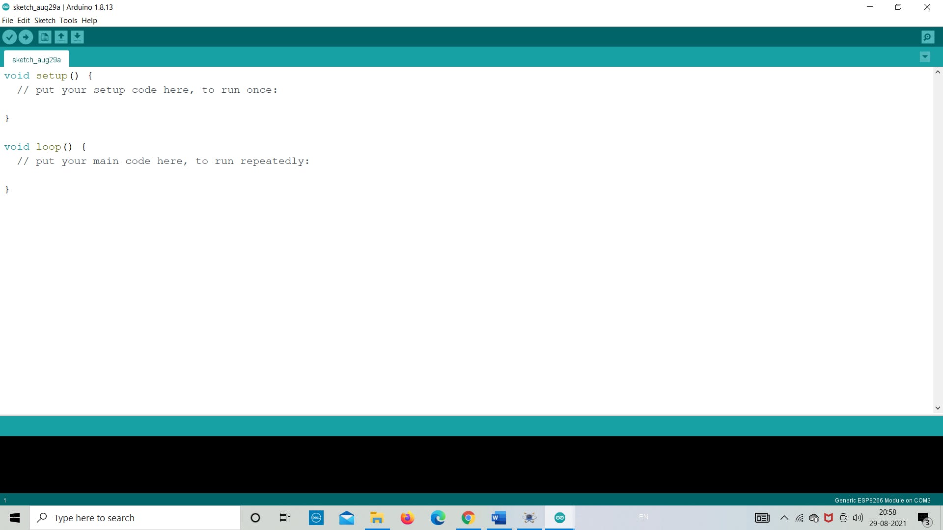
第 1 步:打开 Arduino IDE
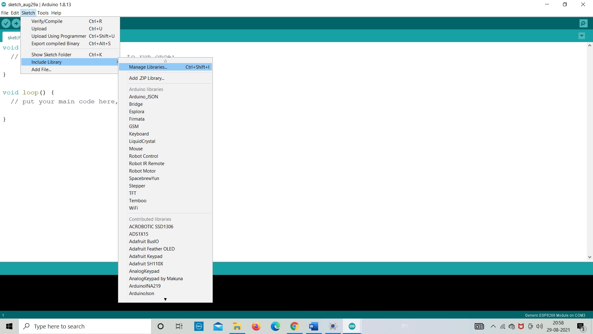
第 2 步:转到“草图”>>“包含库”>>“管理库”
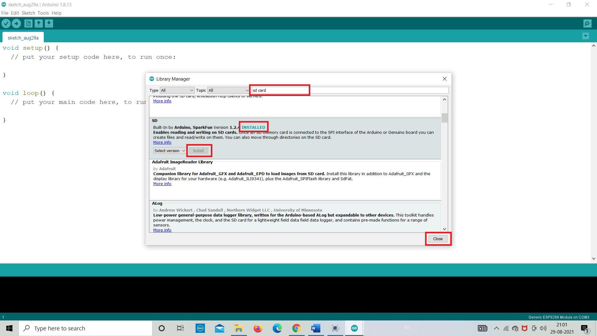
第 3 步:在搜索栏中搜索“SD”并从那里“安装”
ii. 创建 Winimage 映像文件
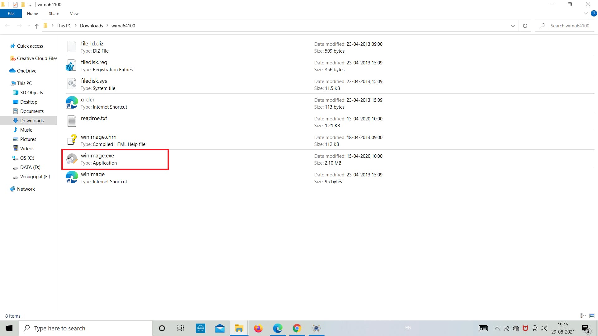
下一步是使用 winimge.exe 软件创建图像文件。在这里,我们将从下载的文件夹中打开它,并将创建 2 MB 大小的文件。该文件将用于将 SD 卡模块中的数据存储为 .txt 格式。
使用 WinImage,您可以在硬盘驱动器或其他媒体上重新创建磁盘映像、查看其内容、提取基于映像的文件、添加新文件和目录、更改格式以及对映像进行碎片整理。
按照下面的图像来了解我们如何创建图像文件。
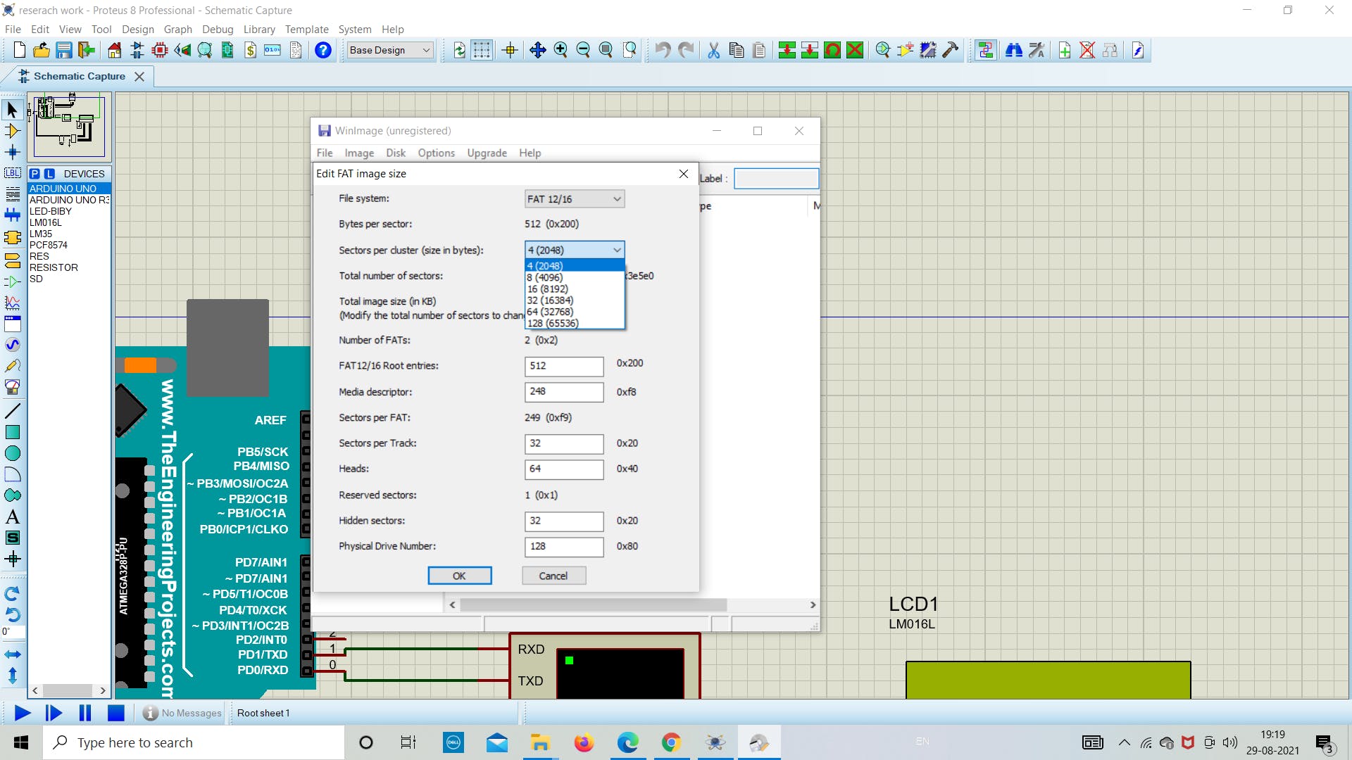
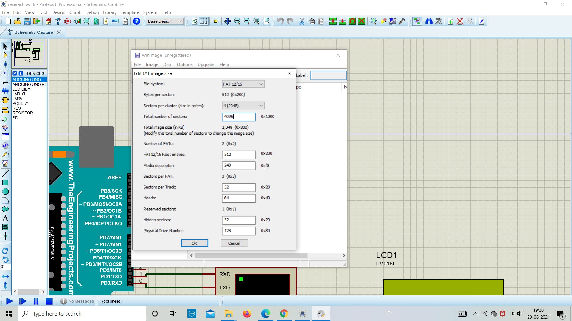
保持 FAT 12/16 和其他参数不受影响,除了图像大小。
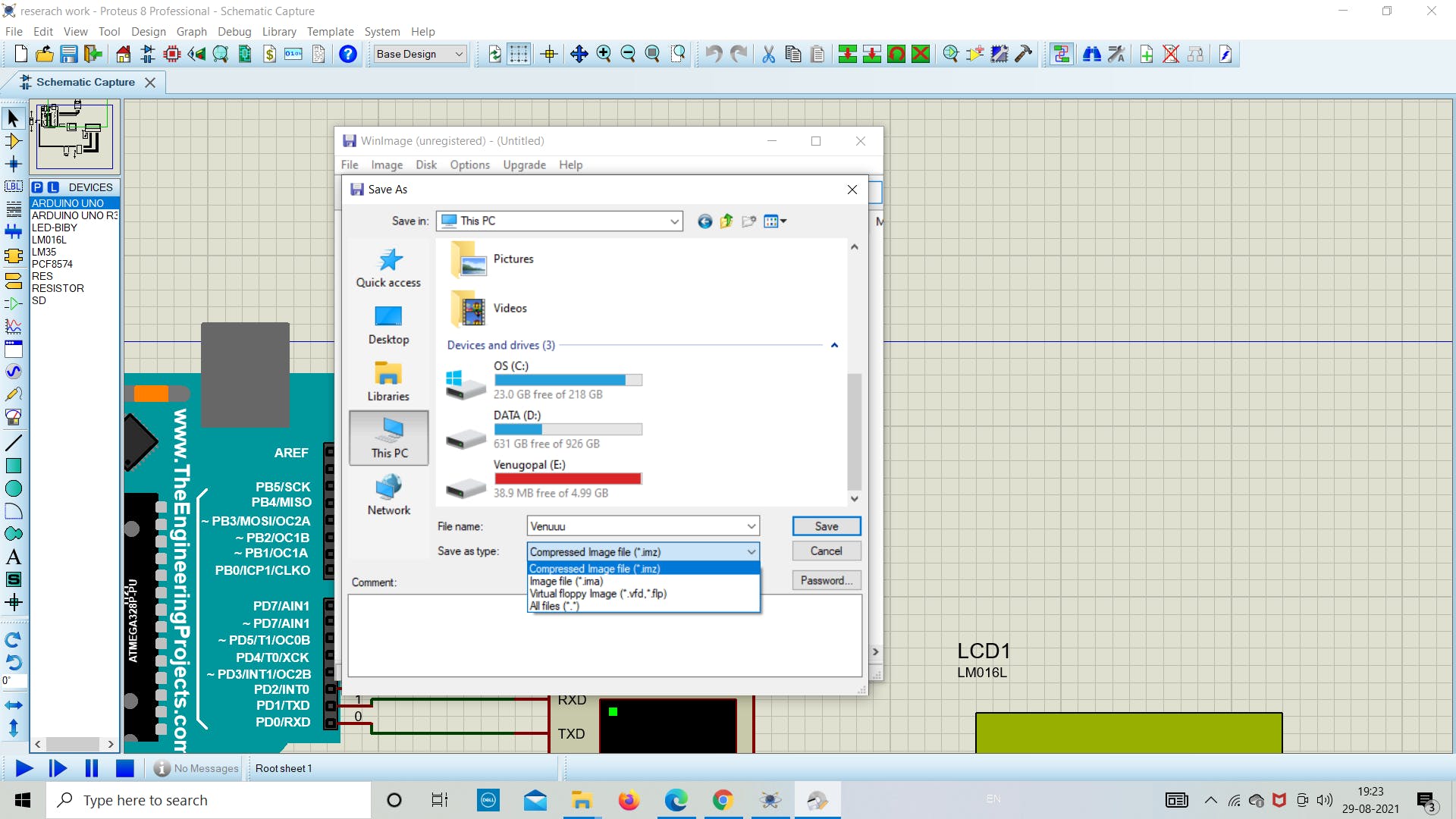
对于这个例子,我们将使用 2 MB 的图像文件,因此创建了相同的图像,如下图所示。我们为图像文件命名为“Venuuu.IMG”
注意:保存文件时不要更改任何扩展名 (*.IMG)。
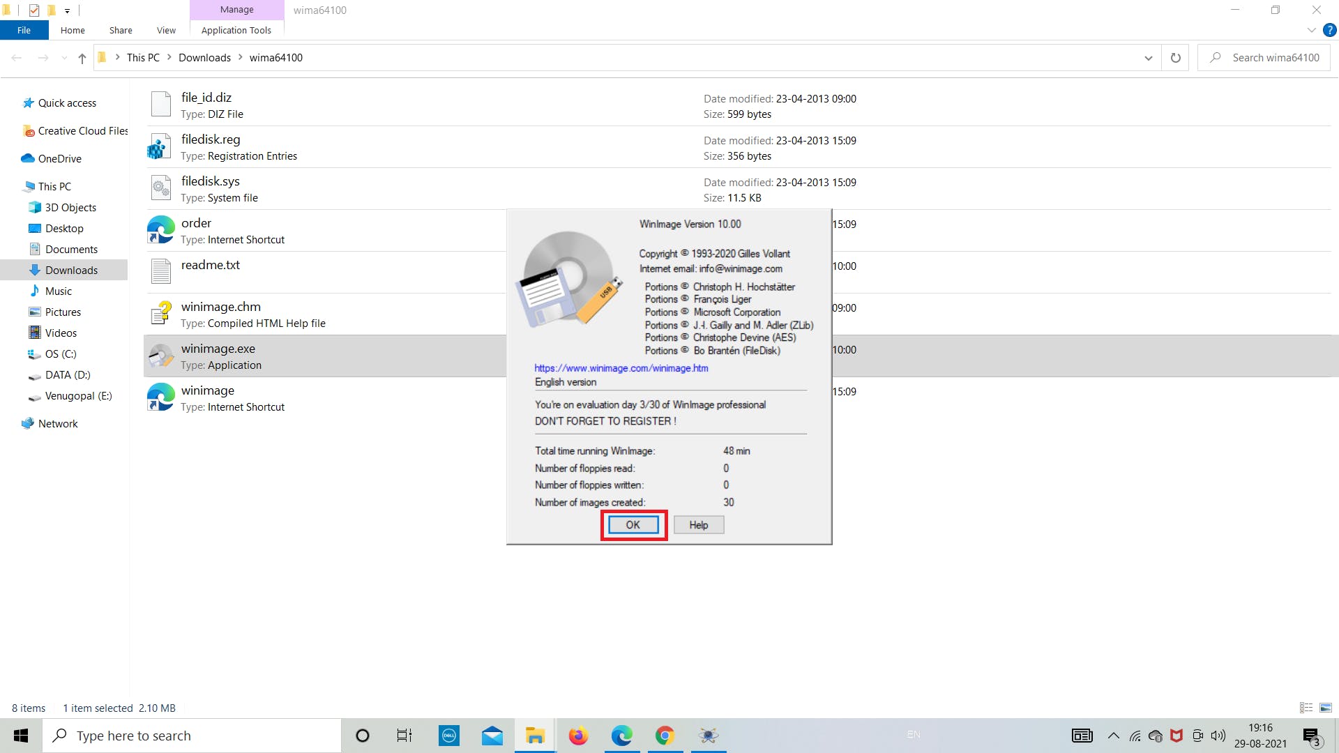
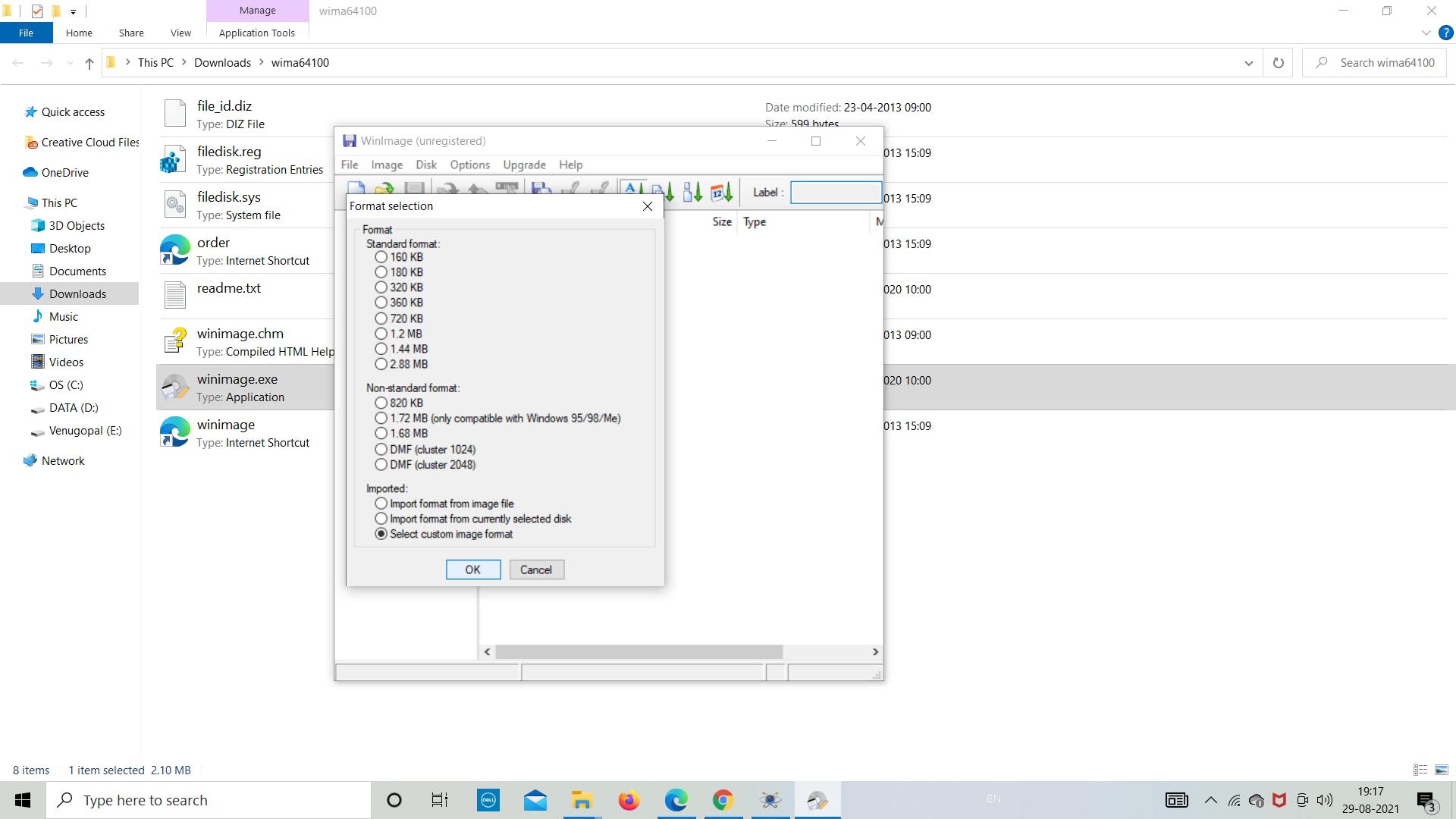
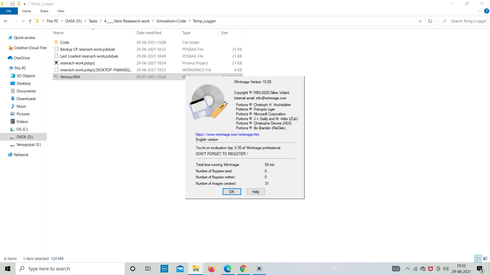
第一步:打开“winimage.exe”文件
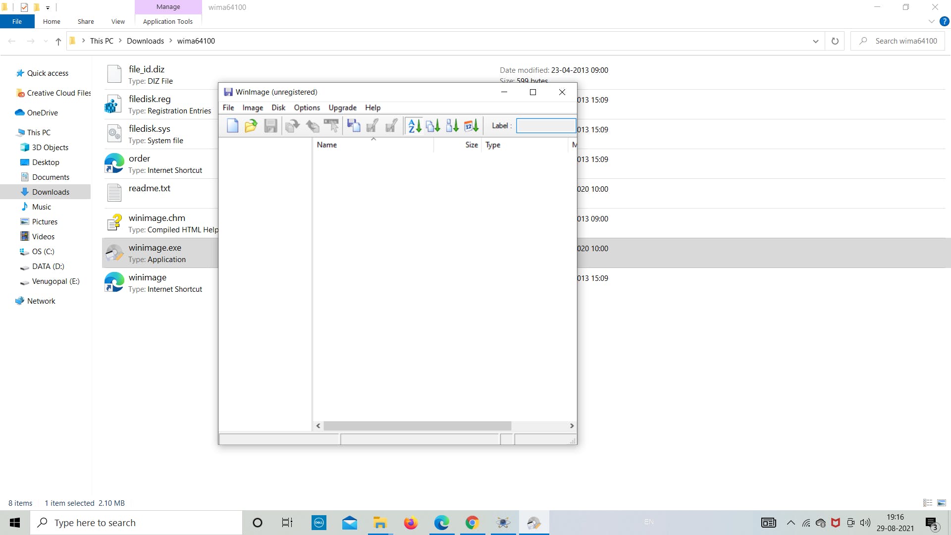
第 2 步:单击“确定”并继续
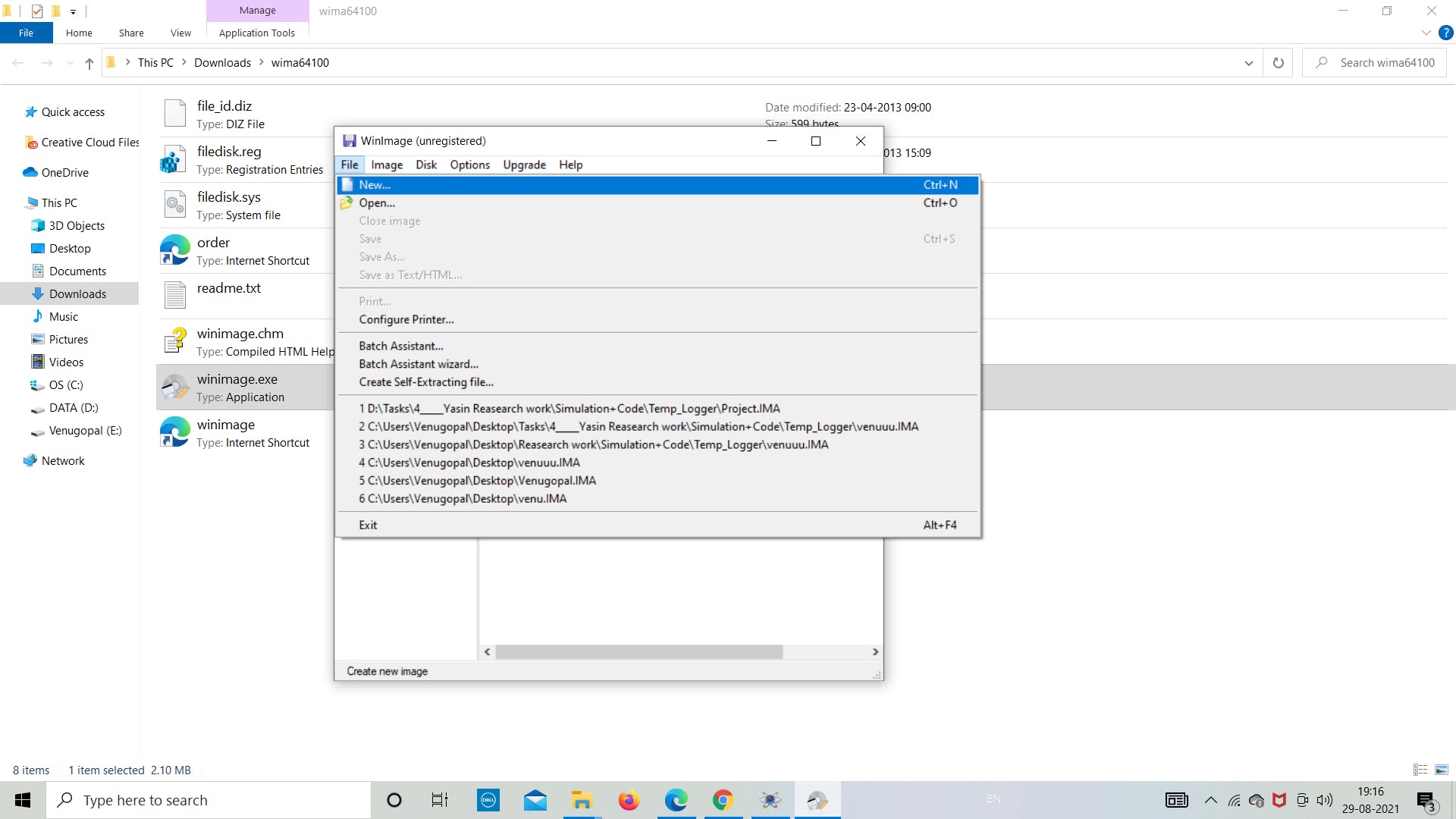
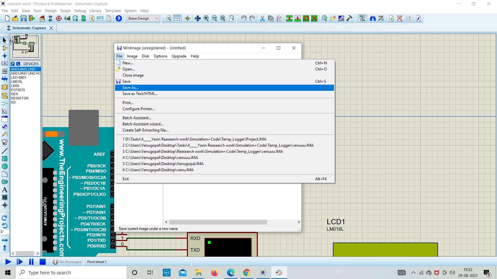
第 3 步:转到左上角的“文件”
第四步:点击“新建”
第 5 步:点击“选择自定义图像格式”
第 6 步:从下拉列表中选择“4 (2048)”
第7步:保持一切原样,然后单击“确定”

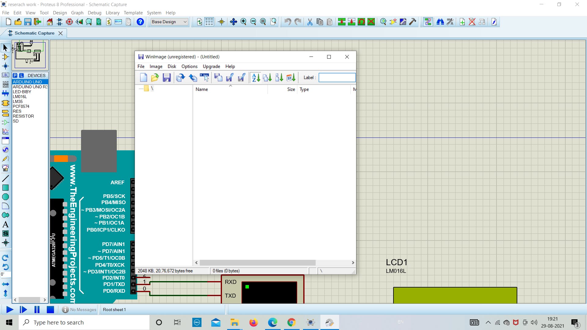
第8步:现在点击“文件”保存文件
第 9 步:现在将文件“另存为”到目标文件夹
1. 模拟与编码
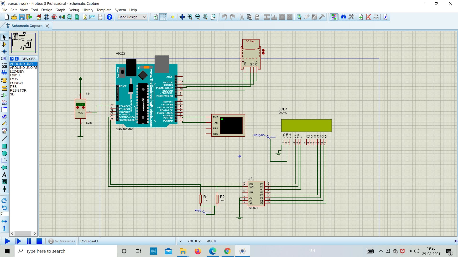
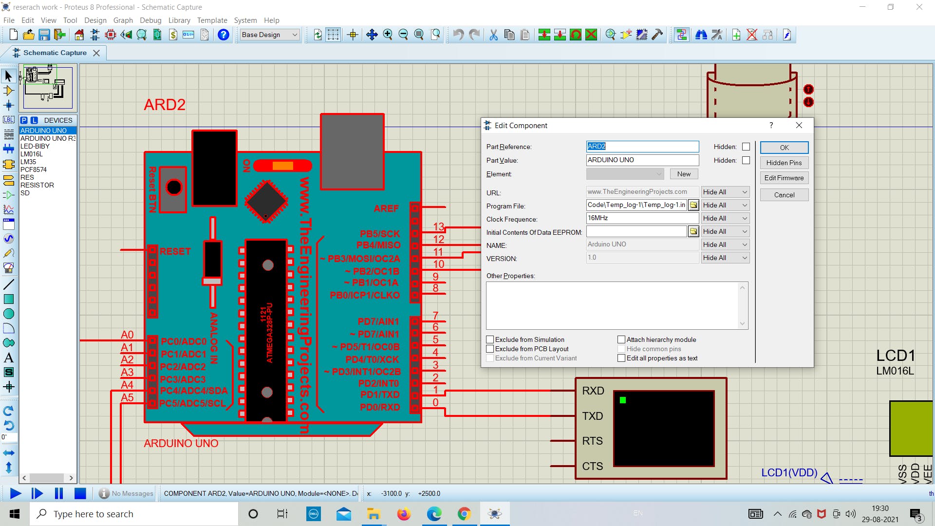
在成功设置了模拟所需的所有先决条件后,现在我们将深入研究在 proteus 中模拟 SD 卡模块的实际部分。现在在 proteus 中打开新文件,然后从软件列表中拖放所需的组件(参考下图),因为我们在上面提到了所有组件的名称。
在这里,我们使用 I2C (PCF8574) 将 LCD 连接到 Arduino,这允许使用较少数量的板上引脚。
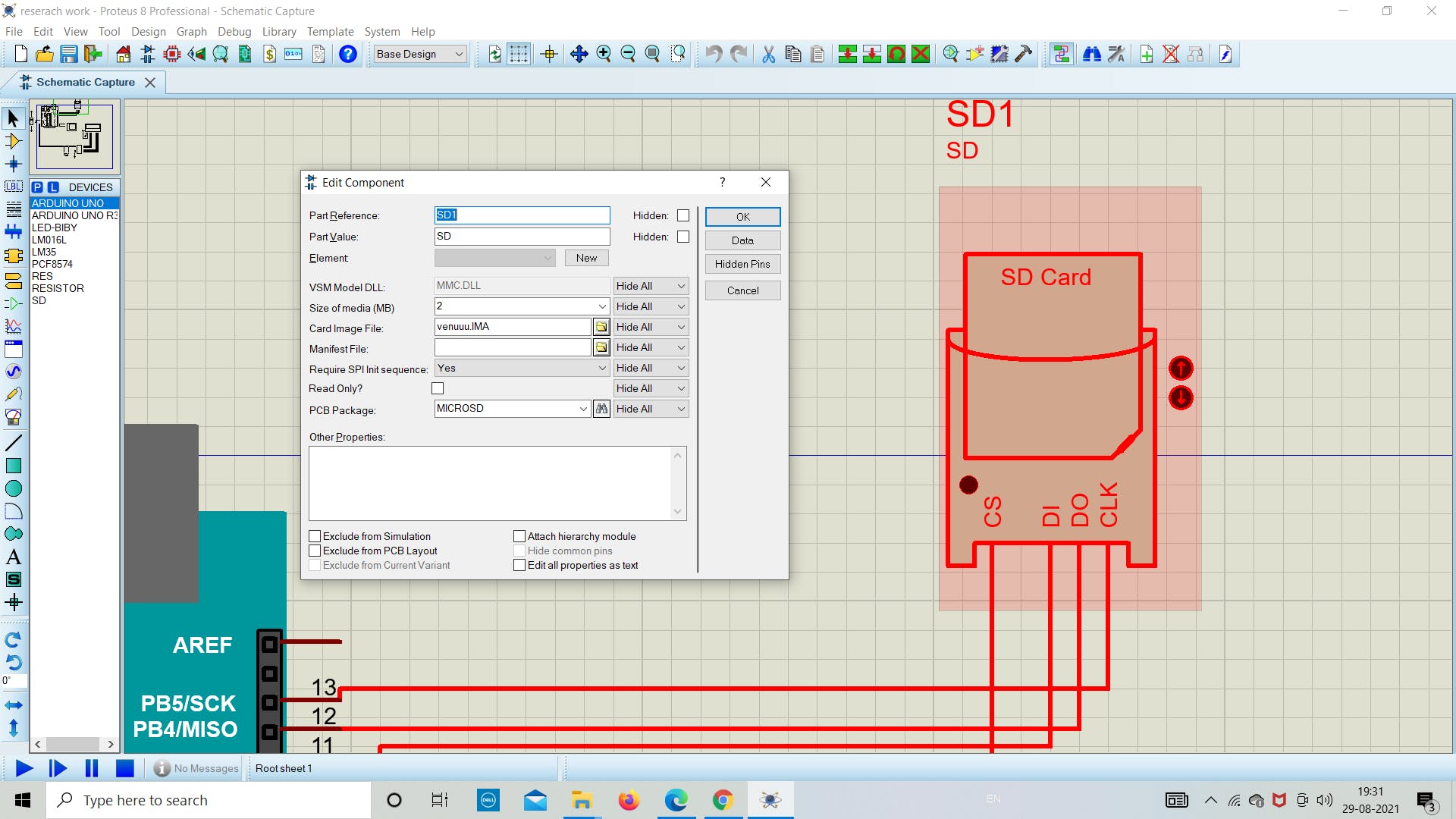
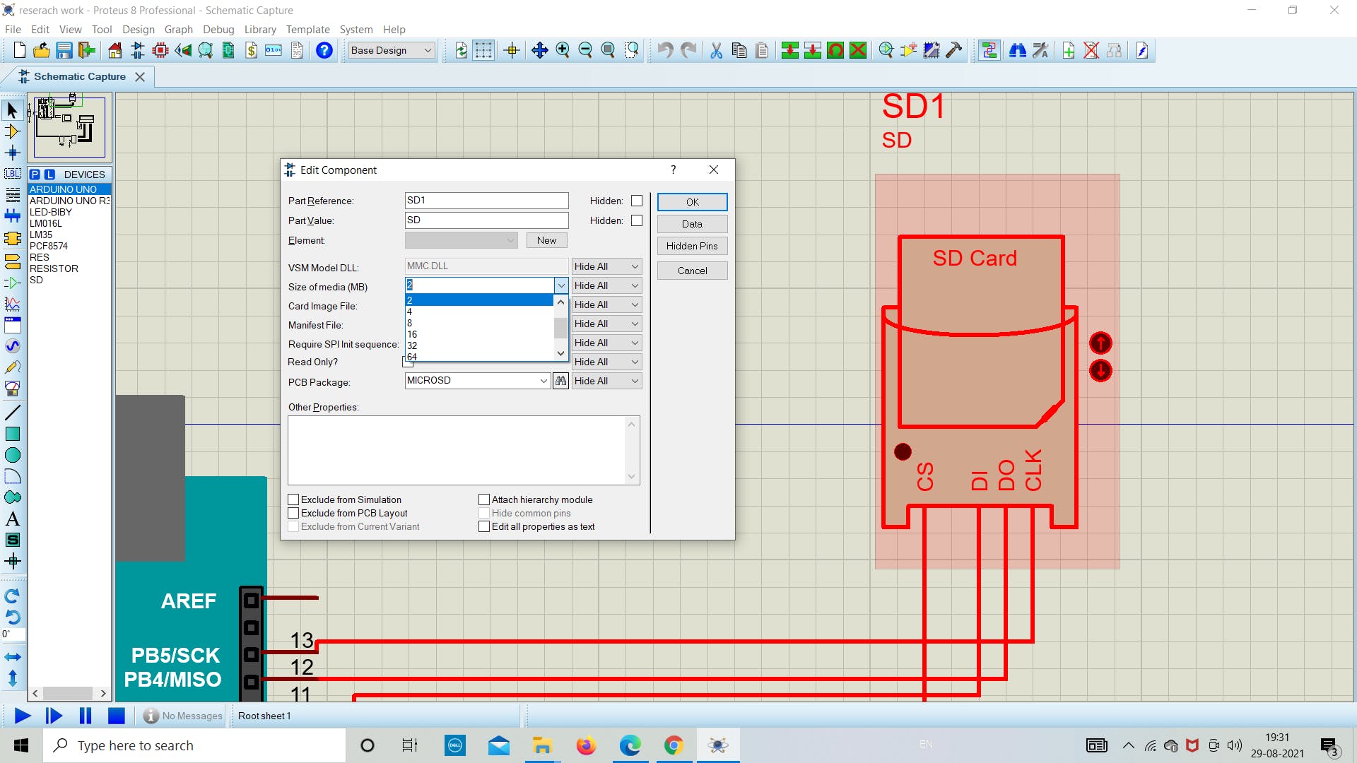
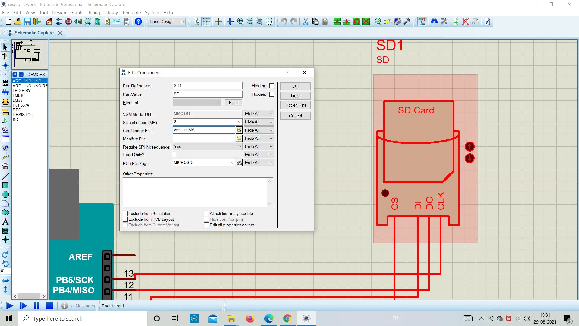
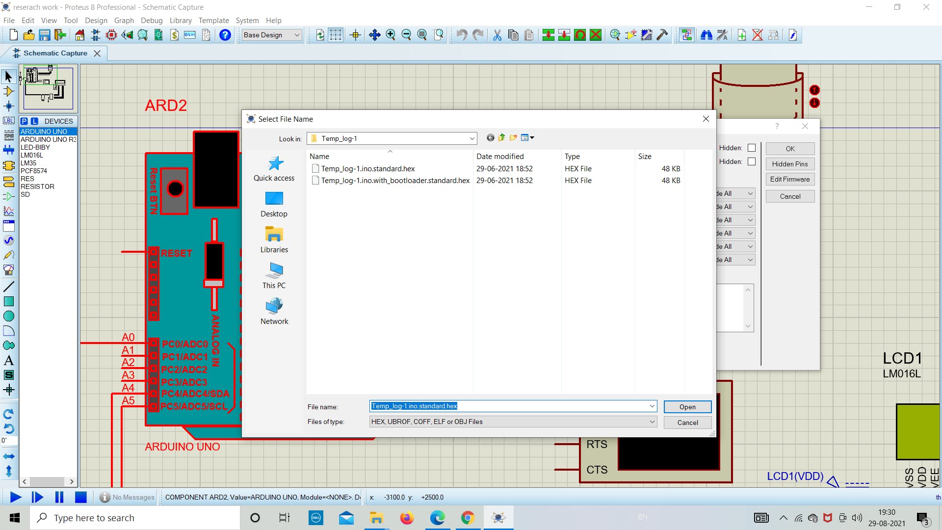
在下一部分中,如下图所示分配 SD 卡模块中图像文件的文件路径,并选择文件大小为 2 MB。
在这个阶段,我们将在 proteus 模拟中的 SD 卡模块中设置卡映像文件路径(下图相同)。
注意:请选择与您创建的图像文件相同的媒体大小(MB)。您可以根据需要创建任何大小的图像文件。
2. 检查 SD 卡的状态
现在我们在 Arduino 中添加下面的草图来了解 SD 卡模块的状态。
下面的草图用于了解我们的 SD 卡是否正确连接到 Arduino。如果没有找出原因并调试它。
上传下面的草图作为成功运行模拟的主要步骤。如果一切顺利,如下图所示,那么您就在正确的轨道上获得最终结果。
// Interfacing Arduino with SD card example (get SD card info)
// include the SD library:
#include
3. 串行监视器输出
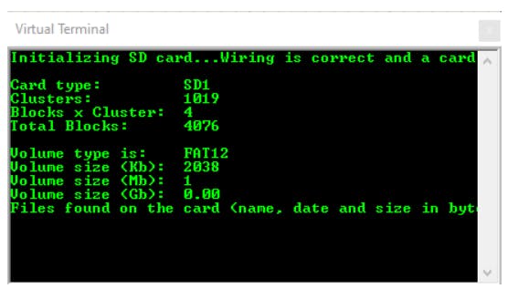
一旦我们在 Arduino 中上传程序,我们将在串行监视器中看到以下任何状态。
1.如果没有卡或Arduino无法连接到它,串口监视器将显示以下消息:
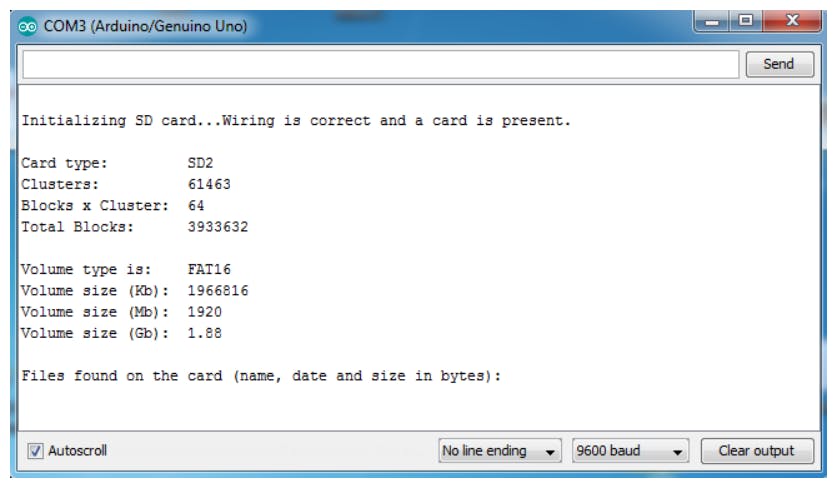
2.如果我们用 FAT16 文件系统放置一个 2 MB 的图像文件,我得到的结果如下所示:
4. 编程、上传和存储
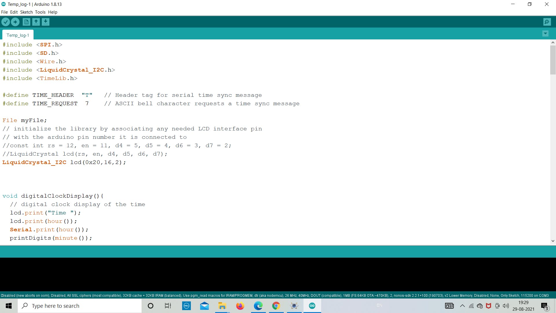
现在我们将生成代码并将其上传到 Arduino,以从 LM35 传感器获取温度值。带有日期和时间的温度值使用 winimage 存储在 .txt 文件中。我们在这里使用 LCD 为用户显示温度,而无需每次打开图像中的 .txt 文件。
将程序保存在所需位置并上传。作为参考,请使用下面的代码了解更多信息。
上传后运行模拟并等待一段时间在 SD 卡中存储 10-20 个读数。
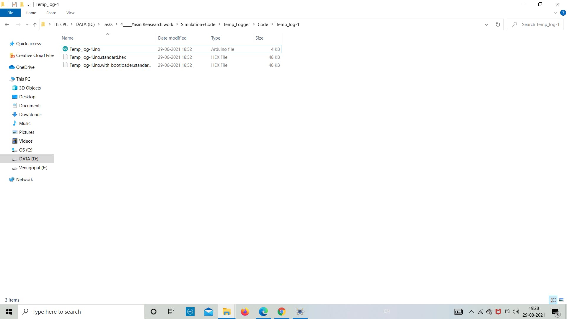
以下是要上传到 Arduino 板的最终草图。参考以下代码并将其保存在目标文件夹中。
#include
5. 导出 SD 卡数据
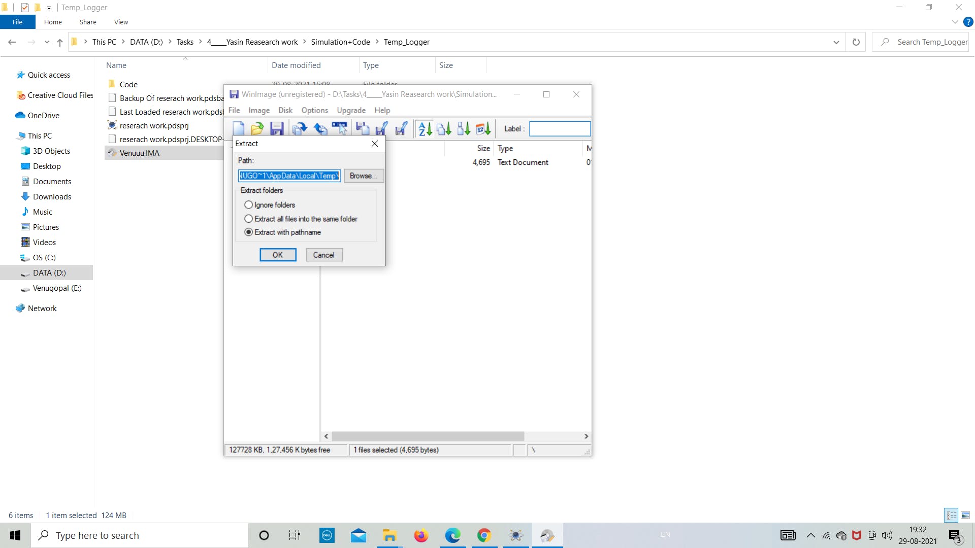
正如我们在模拟部分所做的那样,现在让我们看看数据是否存储在图像文件中。
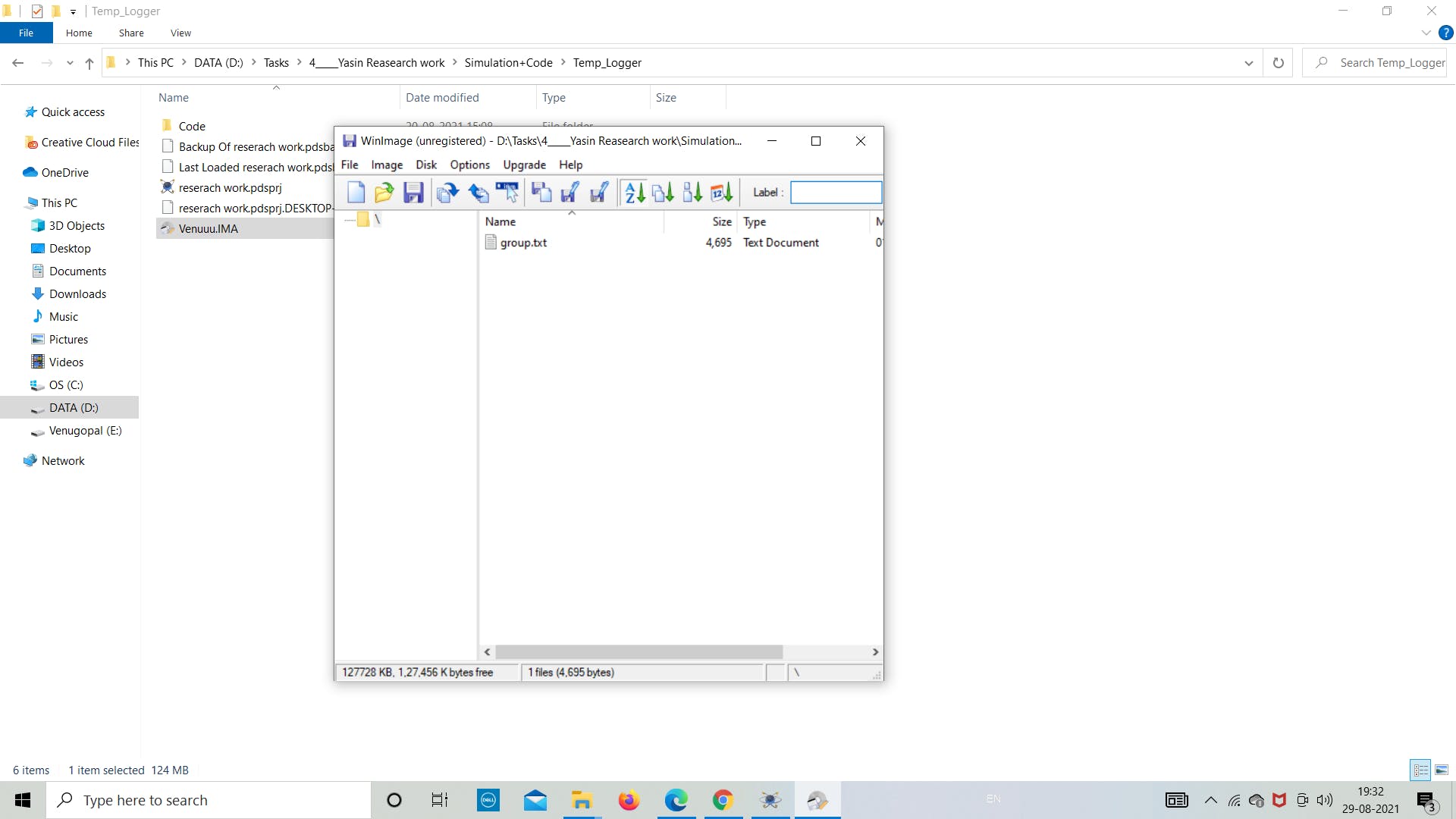
让我们打开“Venuuu.IMG”文件来查看图像文件中的内容。
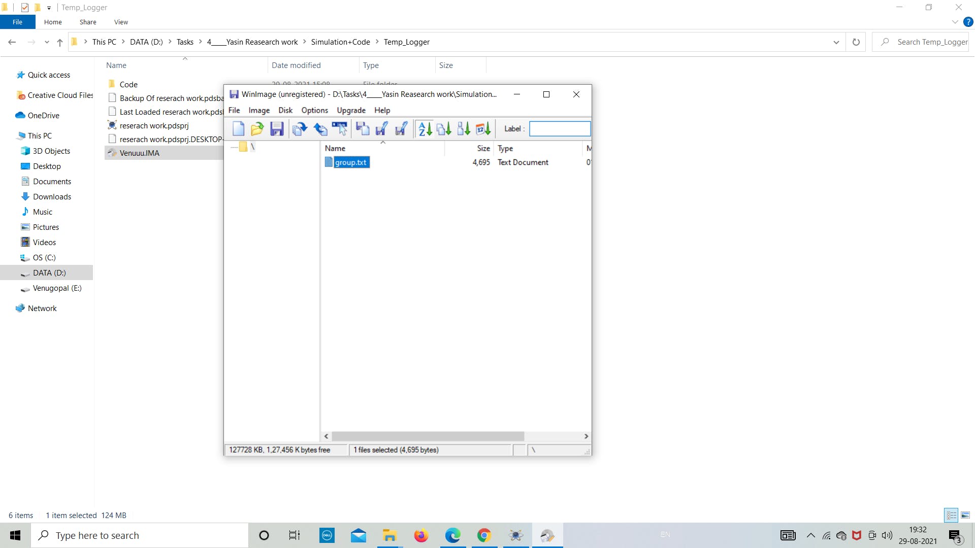
如下图所示,我们可以看到在图像文件中创建了名为“group.txt”的.txt文件。现在我们将通过双击它来导出文件。然后它会自动打开文件,我们可以看到里面存储的温度数据。
按照下图重新创建实验。
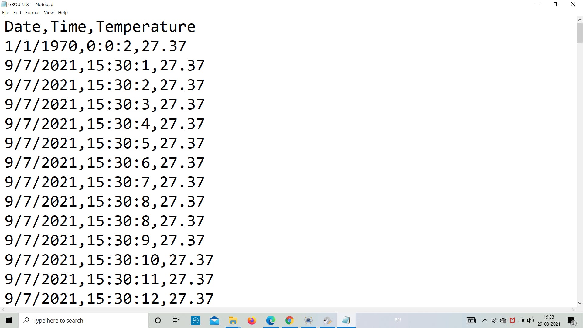
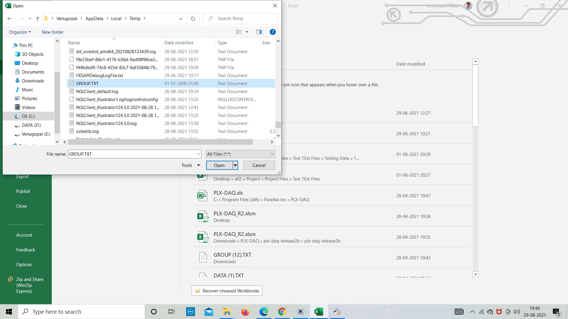
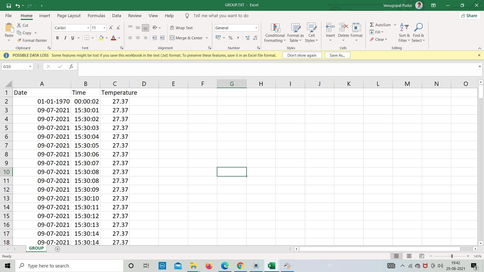
现在我们打开 excel 将文件转换为 excel 格式,以便根据数据或任何其他我们想要的目的绘制图形。
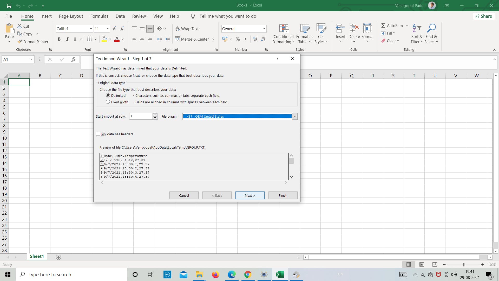
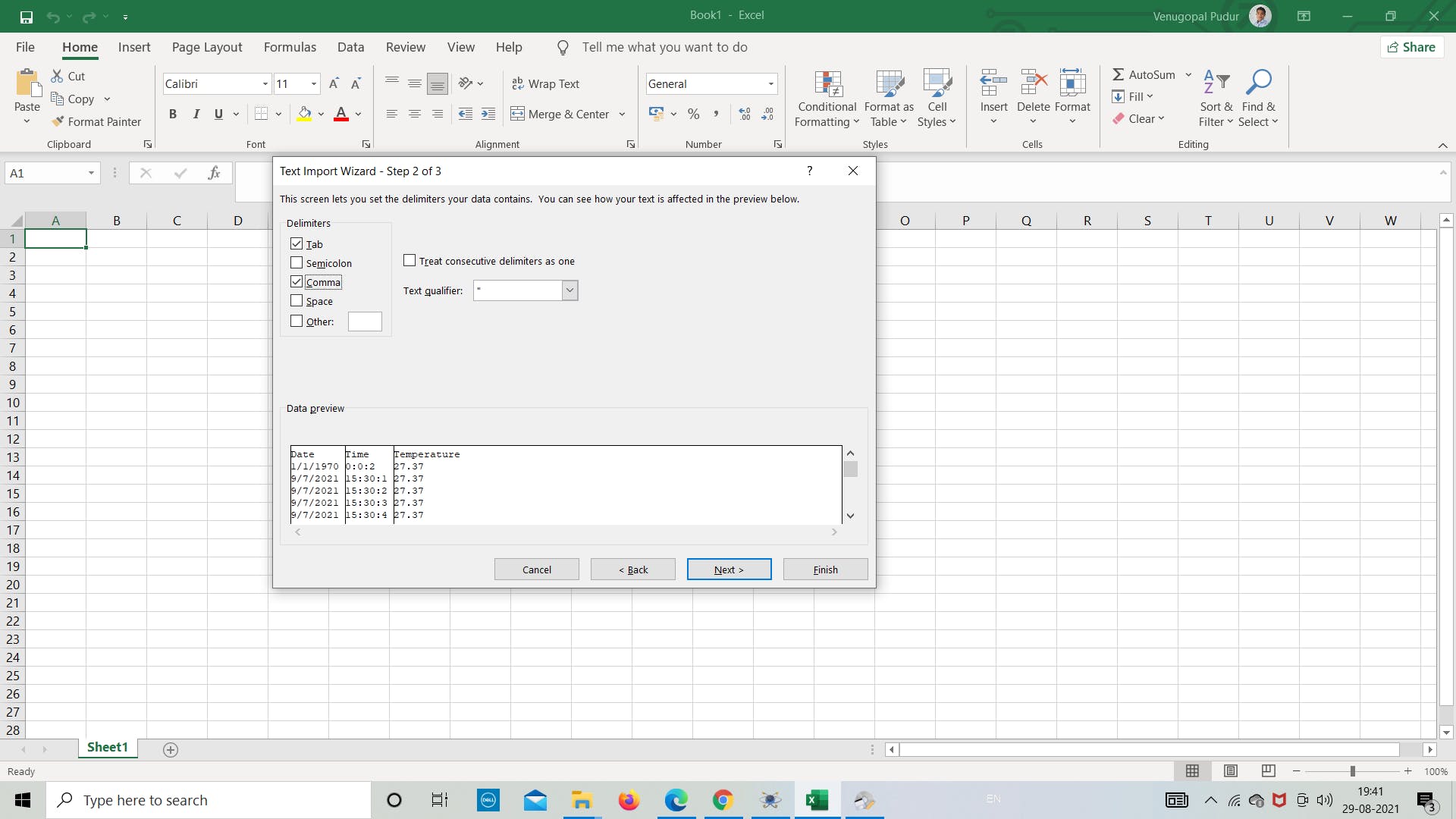
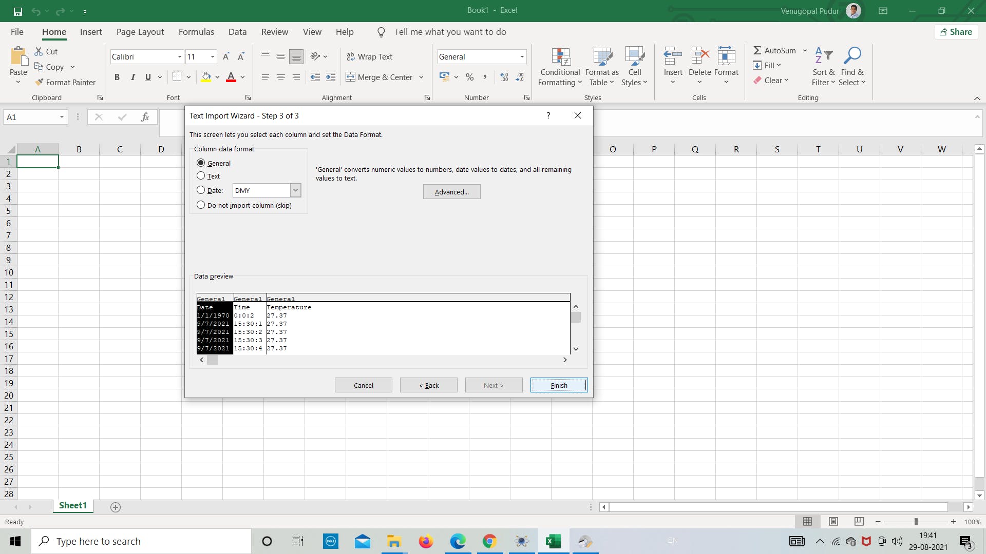
打开 .txt 文件并将分隔符设置为用逗号分隔以将数据分隔为列,然后根据需要继续分析数据。
这都是关于使用 SD 卡模块在 Proteus 中进行的简单模拟。
感谢您阅读本文,祝您有美好的一天!
- CEPARK SD卡模块原理图
- Arduino的DIY SD卡模块
- SD卡2.0协议资料英文版 0次下载
- 基于SPI协议的SD卡读写说明 49次下载
- SD卡的99SE封装库免费下载 43次下载
- SD卡的99SE封装库免费下载 13次下载
- 使用单片机实现SD卡读写的资料和程序免费下载
- 如何实现单片机读写SD卡的底层驱动程序
- 如何使用单片机读写SD卡
- SD卡资料 7次下载
- SD卡要点说明 265次下载
- SD卡分类简介
- SD卡命令解释
- sd卡-mmc卡-CPU说明资料
- sd卡量产工具,下载
- 贴片式SD卡功能介绍【MK SD NAND】 385次阅读
- sd卡是什么有什么用途 TF卡和SD卡有什么区别 3858次阅读
- sd卡是什么有什么用途 TF卡和SD卡有什么区别 2015次阅读
- SD卡的分类以及常见属性 3686次阅读
- TF卡和SD卡的区别有哪些? 8253次阅读
- 怎么通过FPGA采取SD模式实现Micro SD卡的驱动 1691次阅读
- SD/micro SD存储卡介绍 1577次阅读
- STM32G0开发笔记:SD卡模块的使用方法 1983次阅读
- 微雪电子SD卡存储模块简介 1593次阅读
- digilent全尺寸SD卡槽模块简介 2662次阅读
- 微雪电子Micro SD卡 存储模块简介 2765次阅读
- 干货 | SD卡/TF卡的PCB布局布线设计要求 2.5w次阅读
- AT89C52单片机与SD卡实现通讯的设计方案 2996次阅读
- spi读取sd卡数据例程 8823次阅读
- mmc卡和sd卡的区别是什么 4.7w次阅读

 上传资料赚积分
下载排行
本周
- 1山景DSP芯片AP8248A2数据手册
- 1.06 MB | 532次下载 | 免费
- 2RK3399完整板原理图(支持平板,盒子VR)
- 3.28 MB | 339次下载 | 免费
- 3TC358743XBG评估板参考手册
- 1.36 MB | 330次下载 | 免费
- 4DFM软件使用教程
- 0.84 MB | 295次下载 | 免费
- 5元宇宙深度解析—未来的未来-风口还是泡沫
- 6.40 MB | 227次下载 | 免费
- 6迪文DGUS开发指南
- 31.67 MB | 194次下载 | 免费
- 7元宇宙底层硬件系列报告
- 13.42 MB | 182次下载 | 免费
- 8FP5207XR-G1中文应用手册
- 1.09 MB | 178次下载 | 免费
本月
- 1OrCAD10.5下载OrCAD10.5中文版软件
- 0.00 MB | 234315次下载 | 免费
- 2555集成电路应用800例(新编版)
- 0.00 MB | 33566次下载 | 免费
- 3接口电路图大全
- 未知 | 30323次下载 | 免费
- 4开关电源设计实例指南
- 未知 | 21549次下载 | 免费
- 5电气工程师手册免费下载(新编第二版pdf电子书)
- 0.00 MB | 15349次下载 | 免费
- 6数字电路基础pdf(下载)
- 未知 | 13750次下载 | 免费
- 7电子制作实例集锦 下载
- 未知 | 8113次下载 | 免费
- 8《LED驱动电路设计》 温德尔著
- 0.00 MB | 6656次下载 | 免费
总榜
- 1matlab软件下载入口
- 未知 | 935054次下载 | 免费
- 2protel99se软件下载(可英文版转中文版)
- 78.1 MB | 537798次下载 | 免费
- 3MATLAB 7.1 下载 (含软件介绍)
- 未知 | 420027次下载 | 免费
- 4OrCAD10.5下载OrCAD10.5中文版软件
- 0.00 MB | 234315次下载 | 免费
- 5Altium DXP2002下载入口
- 未知 | 233046次下载 | 免费
- 6电路仿真软件multisim 10.0免费下载
- 340992 | 191187次下载 | 免费
- 7十天学会AVR单片机与C语言视频教程 下载
- 158M | 183279次下载 | 免费
- 8proe5.0野火版下载(中文版免费下载)
- 未知 | 138040次下载 | 免费


 工商网监
工商网监
评论