检测任务
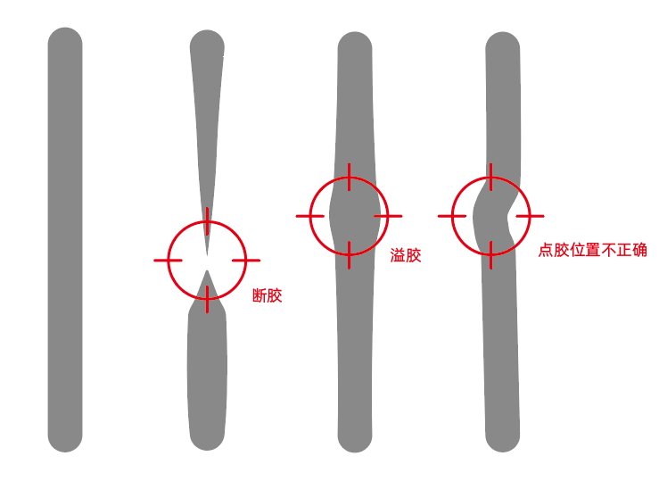
点胶检查检测以下缺陷:
1.缺少粘合胶的部分(断胶)
2.粘合剂过多或过少的部分(溢胶、缺胶)
3.粘合胶离其预定位置太远(点胶偏移)
halcon对应示例程序:
apply_bead_inspection_model.hdev
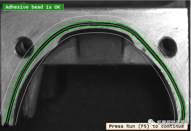
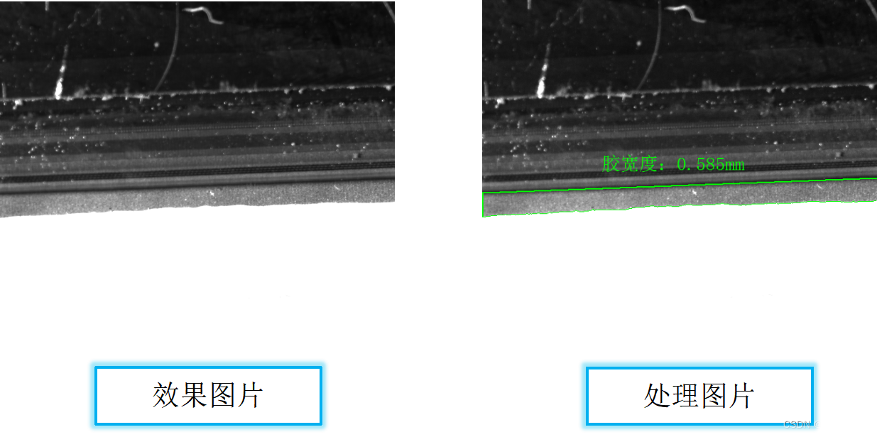
效果图示:
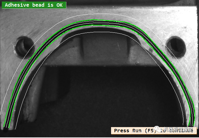
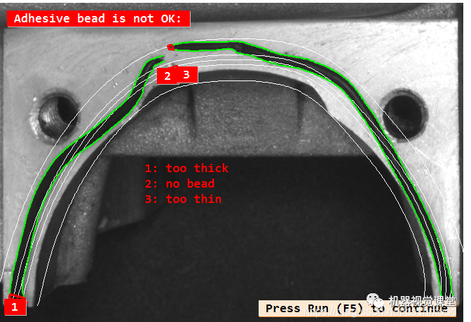
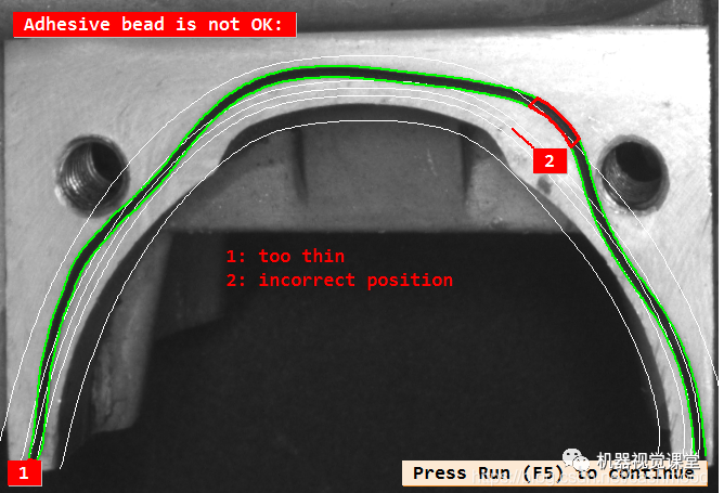
检测思路
示例程序的图像处理思路:
1.使用halcon的可变形模板匹配,将检测物品转正,方便检测
这里我们用的较少,因为我们平时在做点胶检测的时候,用普通的模板匹配,还有普通的2D仿射变换就可以保证图像的一致性。
2.定义粘合胶条的参考路径,以及胶条的宽度,还有误差容忍值
注意,这里halcon的官方例程是给了一个轨迹的点集,我们在实际的检测中,可以使用CAD图纸导入或者手绘路径,完成此步骤。关于CAD图纸导入halcon我会出一期教学博客,写完了把链接贴上来。
3. 利用算子create_bead_inspection_model 创建点胶轨迹模型
创建点胶轨迹的模型,相当于我们使用模板匹配时候用到的穿件模板算子,也不难的。到第三步,我们已经完成了创建模板与点胶轨迹模型的步骤,准备工作都进行完毕,接下来就要进行检测了。
4.校正胎圈的位置,并生成四条平行轮廓,进行显示
显示一下前面准备工作的结果,包括胶轨迹的样子,可容许胶轨迹范围等。
5.读入待检测图像,并进行校正,最后利用算子apply_bead_inspection_model进行点胶轨迹检测
从这一步开始,就使用前面几部的模板,进行点胶轨迹的检测了。首先我们先把图片进行一个仿射变换,转正图片,让我们处理的点胶区域每次都保持一致。这样极大地减小了处理难度。再调用apply_bead_inspection_model进行点胶轨迹检测,就检测完成啦。是不是并不难。
6.根据不同的检测类型在窗口上进行相关显示
最后搞个交互界面显示一下结果就OK了啦。
点胶质量检测代码及解析
在本例中,图片矫正使用平面可变形匹配。
dev_update_off ()
首先使用仿射变换将图片转正,之后创建平面可变形模模板
这一步就是为了让每次处理的图片一致性好。
prepare_alignment (RegionPart, RowT, ColumnT, ModelID)
求取检测区域的最小矩形,这样的好处是只对需要进行图像处理的区域进行处理,使算法速度增加。
smallest_rectangle1 (RegionPart, PartRow1, PartColumn1, PartRow2, PartColumn2)
定义点胶轨迹的参考路径
//这里使用轨迹点集创建点胶轨迹,也可以通过在参考图像上绘制该路径来生成,例如使用算子draw_nurbs.
gen_contour_nurbs_xld (ContourRef, [701.767,626.953,538.867,443.54,390.447,360.28,354.247,363.9,400.1,458.02,509.907,588.34,659.533,696.94], [319.24,336.133,367.507,431.46,489.38,546.093,646.247,722.267,776.567,826.04,869.48,912.92,934.64,929.813], ‘auto’, [15,15,15,15,15,15,15,15,15,15,15,15,15,15], 3, 1, 5)
定义点胶轨迹模板创建变量
TargetWidth := 14
WidthTolerance := 7
PositionTolerance := 30
Polarity := ‘dark’
创建点胶轨迹模板
//参数说明:参考轮廓(ContourRef);胶轨迹标准宽度(TargetWidth);胶轨迹宽度误差大小(WidthTolerance);胶轨迹宽所在的区域范围(PositionTolerance);胶轨迹颜色(Polarity);进行处理的sigma与阈值([], []);创建出的模板(BeadInspectionModel)
create_bead_inspection_model (ContourRef, TargetWidth, WidthTolerance, PositionTolerance, Polarity, [], [], BeadInspectionModel)
读入图片进行显示点胶轨迹、描述信息等
read_image (Image, ‘bead/adhesive_bead_01’)
矫正图像,使图像与之前的图像保持较好的一致性
align_bead (Image, ImageAligned, ModelID, RowT, ColumnT) //校正
创建两个平行轮廓,用于显示正确点胶轨迹的宽度,并将两个轮廓合并到一个变量中
gen_parallel_contour_xld (ContourRef, ModelSide1, ‘regression_normal’, TargetWidth * 0.5)
gen_parallel_contour_xld (ContourRef, ModelSide2, ‘regression_normal’, -TargetWidth * 0.5)
concat_obj (ModelSide1, ModelSide2, ModelSides)
创建两个平行轮廓,用于显示正确点胶轨迹容许范围,并将两个轮廓合并到一个变量中
gen_parallel_contour_xld (ContourRef, PositionToleranceSide1, ‘regression_normal’, PositionTolerance)
gen_parallel_contour_xld (ContourRef, PositionToleranceSide2, ‘regression_normal’, -PositionTolerance)
concat_obj (PositionToleranceSide1, PositionToleranceSide2, PositionToleranceSides)
halcon显示操作相关操作
dev_close_window ()
dev_open_window_fit_size (0, 0, PartColumn2 - PartColumn1 + 1, PartRow2 - PartRow1 + 41, -1, -1, WindowHandle)
set_display_font (WindowHandle, 16, ‘mono’, ‘true’, ‘false’)
dev_set_part (PartRow1 - 20, PartColumn1, PartRow2 + 20, PartColumn2)
dev_display (ImageAligned)
dev_set_line_width (2)
dev_set_color (‘green’)
dev_display (ContourRef) //粘合胶条的参考路径
dev_set_line_width (1)
dev_display (ModelSides) //胶条的宽度
dev_set_color (‘yellow’)
dev_display (PositionToleranceSides) //容许点胶范围
显示描述文本
Message := ‘Correct adhesive bead and the reference contour. The’
Message[1] := ‘yellow contours indicate the range of position tolerance.’
disp_message (WindowHandle, Message, ‘window’, 12, 12, ‘black’, ‘true’)
disp_continue_message (WindowHandle, ‘black’, ‘true’)
stop ()
*
开始读入图片进行检测
TextOffset := 20 //偏移值
NumImages := 7
for Index := 1 to NumImages by 1
read_image (Image, ‘bead/adhesive_bead_’ + Index$‘02’)
矫正图片
align_bead (Image, ImageAligned, ModelID, RowT, ColumnT)
使用之前生成的点胶轨迹模板,进行点胶轨迹检测
//参数说明:进行检测的图像(ImageAligned);胶轨迹左轮廓(LeftContour);胶轨迹右轮廓(RightContour);胶轨迹宽缺陷所在位置(ErrorSegment);使用的模板(BeadInspectionModel);缺陷种类(ErrorType)
apply_bead_inspection_model (ImageAligned, LeftContour, RightContour, ErrorSegment, BeadInspectionModel, ErrorType)
显示点胶轨迹,检测结果等相关信息
dev_display (ImageAligned)
dev_set_line_width (1)
dev_set_color (‘white’)
dev_display (ContourRef)
dev_display (ModelSides)
dev_display (PositionToleranceSides)
dev_set_line_width (2)
dev_set_color (‘green’)
dev_display (LeftContour) //检测出的内部XLD
dev_display (RightContour) //检测出的外部XLD
dev_set_color (‘red’)
dev_display (ErrorSegment) //错误部分区域
if (|ErrorType| == 0)
没有错误信息,显示OK
Message := ‘Adhesive bead is OK’
disp_message (WindowHandle, Message, ‘window’, 12, 12, ‘white’, ‘forest green’)
disp_continue_message (WindowHandle, ‘black’, ‘true’)
stop ()
else
OK,并且显示缺陷种类,标识缺陷位置
:= ‘Adhesive bead is not OK:’
ErrorClasses := [‘no bead’,‘too thin’,‘too thick’,‘incorrect position’]
for ClassIndex := 0 to |ErrorClasses| - 1 by 1
Class := ErrorClasses[ClassIndex]
ErrorIndices := find(ErrorType,Class)
if (ErrorIndices != -1)
select_obj (ErrorSegment, SelectedSegments, ErrorIndices + 1)
dev_set_color (‘red’)
dev_set_line_width (3)
if (Class != ‘no bead’)
gen_display_segments (SelectedSegments, LeftContour, RightContour, ErrorParts)
dev_display (ErrorParts)
else
dev_display (SelectedSegments)
endif
area_center_points_xld (SelectedSegments, Area, Row, Column)
for E := 0 to |ErrorIndices| - 1 by 1
disp_message (WindowHandle, ErrorIndices[E] + 1, ‘image’, Row[E], Column[E] - TextOffset, ‘white’, ‘red’)
TextOffset := 20 - TextOffset
endfor
endif
endfor
disp_message (WindowHandle, Message, ‘window’, 12, 12, ‘white’, ‘red’)
disp_message (WindowHandle, [1:|ErrorType|] + ': ’ + ErrorType, ‘image’, 500, 500, ‘red’, ‘false’)
if (Index < NumImages)
disp_continue_message (WindowHandle, ‘black’, ‘true’)
stop ()
endif
endif
endfor
释放所有模板句柄
clear_bead_inspection_model (BeadInspectionModel)
clear_deformable_model (ModelID)
图示处理思路
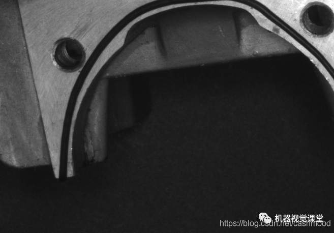
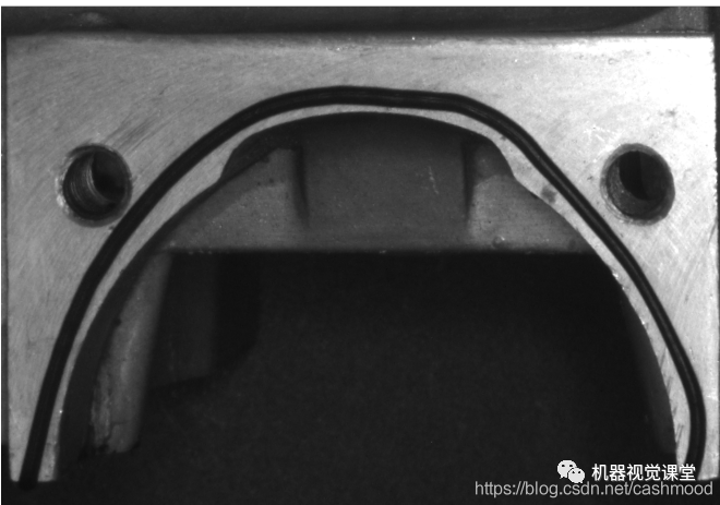
1、使用符合要求图像,创建模板
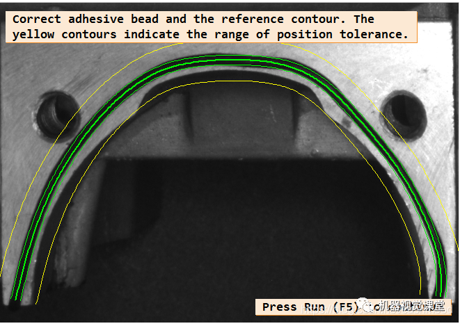
2、读入新图像,矫正图像(图像仿射变换)
矫正前图像:
矫正后图像:
3、使用创建的模板检测点胶轨迹,得到结果
-
图像处理
+关注
关注
27文章
1289浏览量
56724 -
CAD
+关注
关注
17文章
1090浏览量
72450 -
模板
+关注
关注
0文章
108浏览量
20561
原文标题:一文学会,胶位偏移、缺胶、断胶、溢胶检测(含源码)
文章出处:【微信号:vision263com,微信公众号:新机器视觉】欢迎添加关注!文章转载请注明出处。
发布评论请先 登录
相关推荐
FPC压合工艺过程中的溢胶现象的产生原因
如何改进光纤涂覆机注胶管堵塞和溢胶和固化时间长等问题的建议说明
FPC柔性线路板溢胶应该怎样去解决
如何解决瞬间胶点胶加工时点胶机胶阀漏胶的问题
我们该如何提高点胶代工时点胶出胶的效果
AVENTK教你如何处理UV胶水点胶断胶问题
芯片点胶GD414硅橡胶胶溢对电阻的影响讨论
FPC电路软板点胶质量——缺胶、胶宽测量视觉检测方案


 一文学会,胶位偏移、缺胶、断胶、溢胶检测(含源码)



评论