spi概述
SPI是串行外设接口(Serial Peripheral Interface)的缩写,是一种高速的,全双工,同步的通信总线,并且在芯片的管脚上只占用四根线,节约了芯片的管脚,同时为PCB的布局上节省空间,提供方便,正是出于这种简单易用的特性,越来越多的芯片集成了这种通信协议,比如 EEPROM,FLASH,实时时钟,AD转换器。 W25Q64 是一款SPI接口的Flash芯片,其存储空间为 64Mbit,相当于8M字节。W25Q64可以支持 SPI 的模式 0 和模式 3,也就是 CPOL=0/CPHA=0 和CPOL=1/CPHA=1 这两种模式。 最近在弄ST和GD的课程,需要GD样片的可以加群申请:6_15061293 。
视频教程
https://www.bilibili.com/video/BV16W4y147R1/
样品申请
https://www.wjx.top/vm/wFGhGPF.aspx#
csdn课程
课程更加详细。
https://download.csdn.net/course/detail/37144
生成例程
这里准备了自己绘制的开发板进行验证。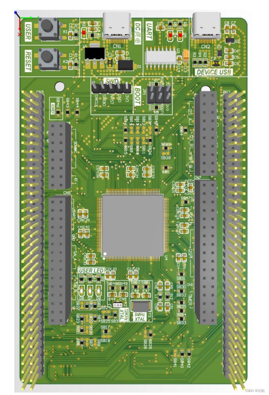
SPI配置
在开发板中有arduino接口,配置这几个接口为spi。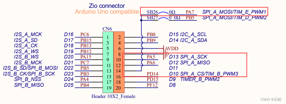
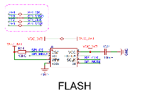
本次实验使用的SPI与Flash通信,配置如下。 SPI的通信原理很简单,它以主从方式工作,这种模式通常有一个主设备和一个或多个从设备,需要至少4根线,事实上3根也可以(单向传输时)。也是所有基于SPI的设备共有的,它们是MISO(主设备数据输入)、MOSI(主设备数据输出)、SCLK(时钟)、CS(片选)。 (1)MISO– Master Input Slave Output,主设备数据输入,从设备数据输出; (2)MOSI– Master Output Slave Input,主设备数据输出,从设备数据输入; (3)SCLK – Serial Clock,时钟信号,由主设备产生; (4)CS – Chip Select,从设备使能信号,由主设备控制。
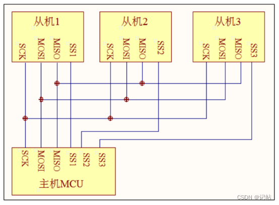
负责通讯的3根线了。通讯是通过数据交换完成的,这里先要知道SPI是串行通讯协议,也就是说数据是一位一位的传输的。这就是SCLK时钟线存在的原因,由SCLK提供时钟脉冲,SDI,SDO则基于此脉冲完成数据传输。数据输出通过 SDO线,数据在时钟上升沿或下降沿时改变,在紧接着的下降沿或上升沿被读取。完成一位数据传输,输入也使用同样原理。因此,至少需要8次时钟信号的改变(上沿和下沿为一次),才能完成8位数据的传输。 时钟信号线SCLK只能由主设备控制,从设备不能控制。同样,在一个基于SPI的设备中,至少有一个主设备。这样的传输方式有一个优点,在数据位的传输过程中可以暂停,也就是时钟的周期可以为不等宽,因为时钟线由主设备控制,当没有时钟跳变时,从设备不采集或传送数据。SPI还是一个数据交换协议:因为SPI的数据输入和输出线独立,所以允许同时完成数据的输入和输出。芯片集成的SPI串行同步时钟极性和相位可以通过寄存器配置,IOinterwetten与威廉的赔率体系 的SPI串行同步时钟需要根据从设备支持的时钟极性和相位来通讯。 最后,SPI接口的一个缺点:没有指定的流控制,没有应答机制确认是否接收到数据。
NOR Flash
NOR Flash是一种非易失闪存威廉希尔官方网站 ,是Intel在1988年创建。是市场上两种主要的非易失闪存威廉希尔官方网站 之一。 以GD25Q64E为例,该 Flash为64M-bit大小,即8192K-Byte。
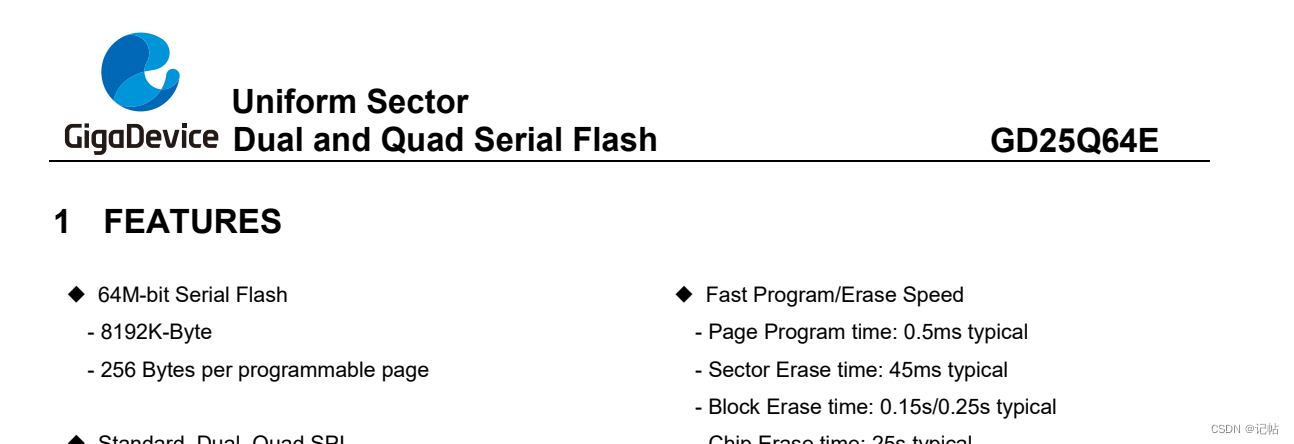
W25Q64将8M的容量分为127个块(Block),每个块大小为64K字节,每个块又分为16个扇区(Sector),每个扇区4K个字节。W25Q64的最小擦除单位为一个扇区,也就是每次必须擦除4K个字节。 即4K16128=8192K=8M
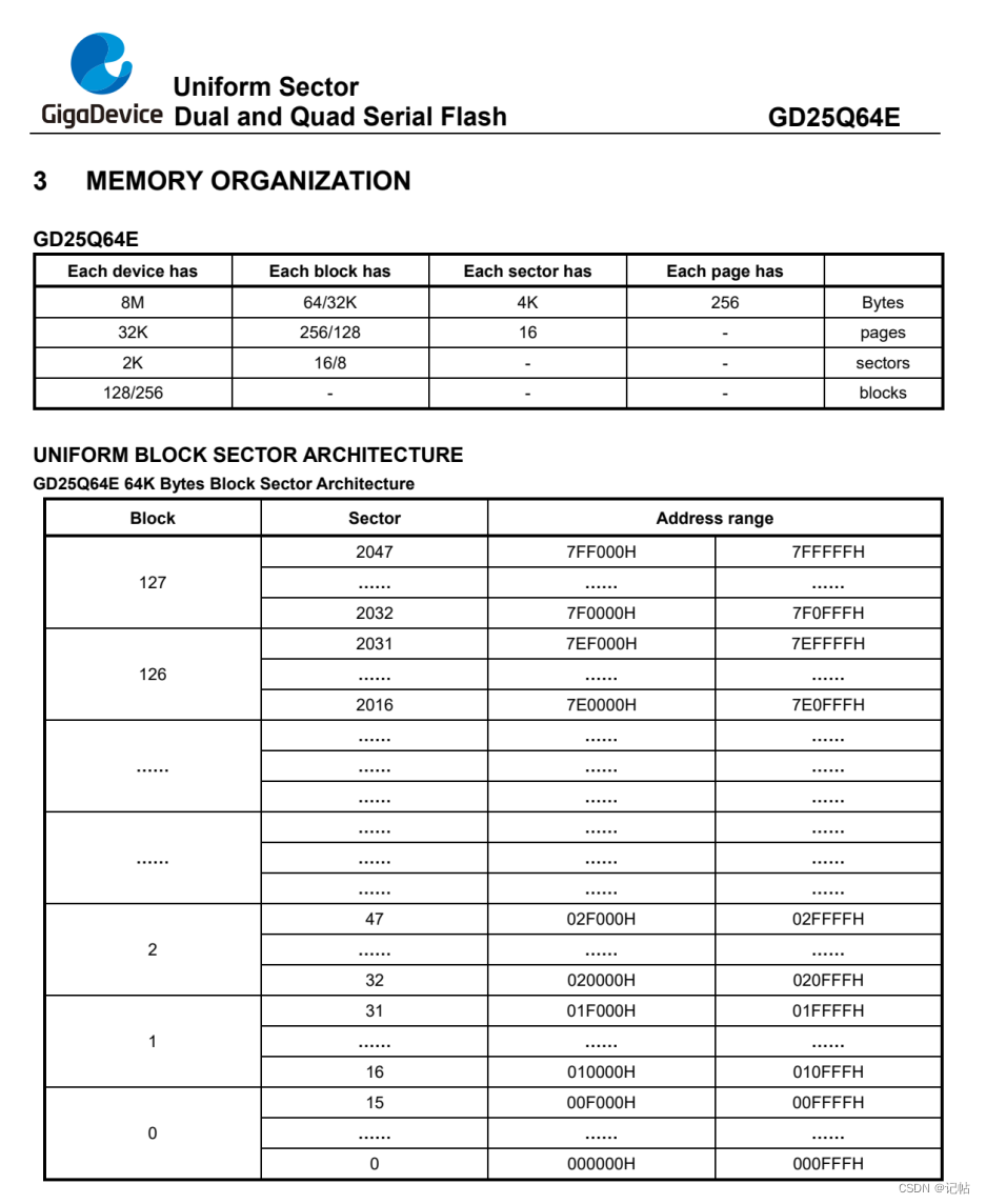
W25Q64的原理及应用
复位初始化
对于复位,需要发送0x66和0x99
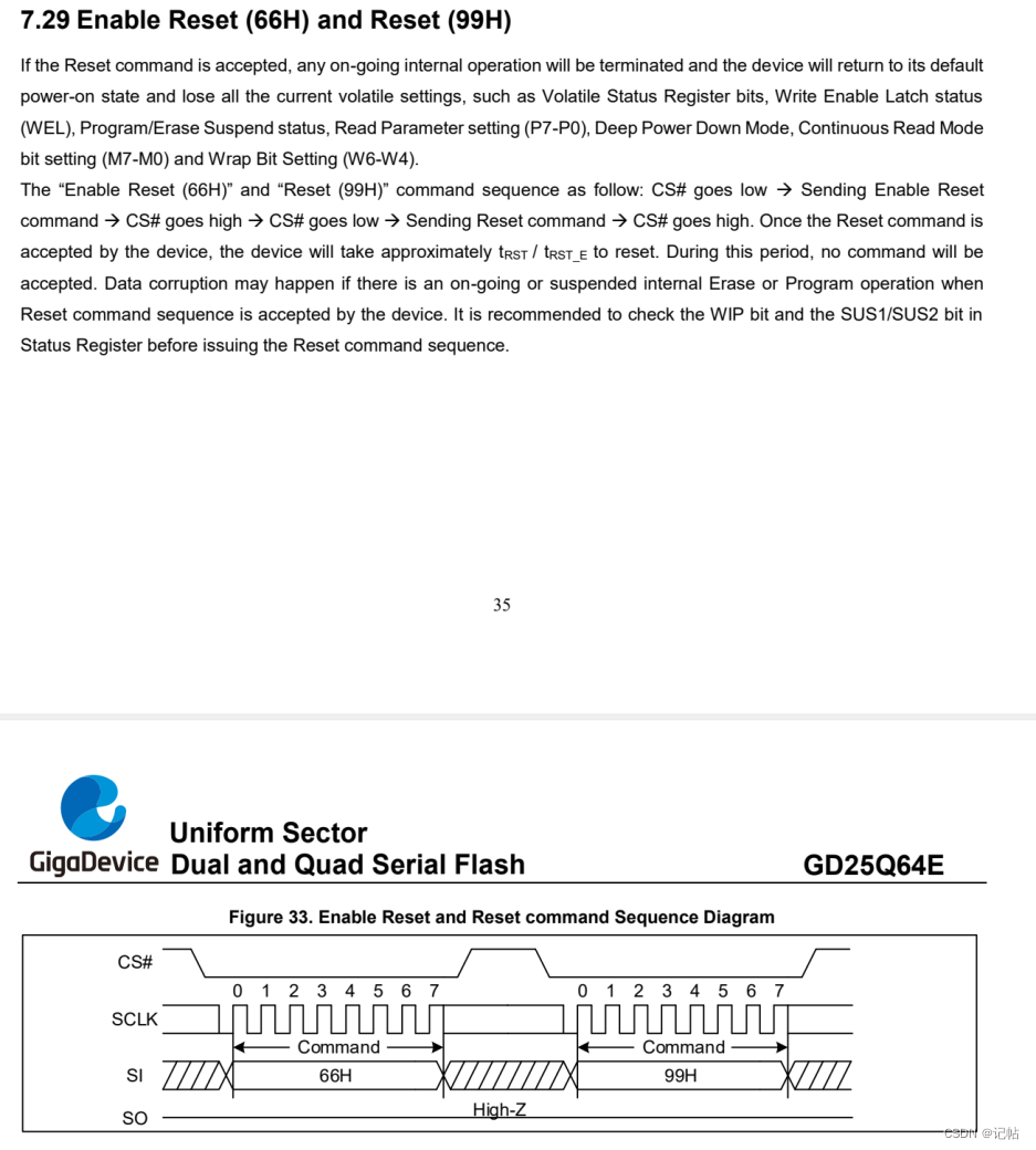
代码中的初始化。
/* Reset Operations */
#define RESET_ENABLE_CMD                     0x66
#define RESET_MEMORY_CMD                     0x99
/**
  * @brief  Initializes the W25Q128FV interface.
  * @retval None
  */
uint8_t BSP_W25Qx_Init(void)
{
    /* Reset W25Qxxx */
    BSP_W25Qx_Reset();

    return BSP_W25Qx_GetStatus();
}

/**
  * @brief  This function reset the W25Qx.
  * @retval None
  */
static void    BSP_W25Qx_Reset(void)
{
    uint8_t cmd[2] = {RESET_ENABLE_CMD,RESET_MEMORY_CMD};
    W25Qx_Enable();
    /* Send the reset command */
    for(int i=0;i< 2;i++){
    spi_SendRcvByte(SPI0,cmd[i]);
}
//    HAL_SPI_Transmit(&hspi1, cmd, 2, W25Qx_TIMEOUT_VALUE);
    W25Qx_Disable();
}

ID
对于兆易创新W25Q64,主要有三种查询ID方式。

可以使用90H查询设备ID,以判断是否是W25Q64设备。
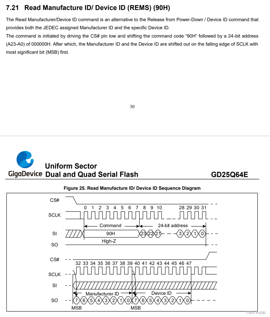
/* Identification Operations */
#define READ_ID_CMD                          0x9F
/**
  * @brief  Read Manufacture/Device ID.
    * @param  return value address
  * @retval None
  */
void BSP_W25Qx_Read_ID(uint8_t *ID)
{
    uint8_t cmd[4] = {READ_ID_CMD,0x00,0x00,0x00};

    W25Qx_Enable();
    /* Send the read ID command */
//    HAL_SPI_Transmit(&hspi1, cmd, 4, W25Qx_TIMEOUT_VALUE);
    /* Reception of the data */
//    HAL_SPI_Receive(&hspi1,ID, 2, W25Qx_TIMEOUT_VALUE);
    for(int i=0;i< 4;i++)
        spi_SendRcvByte(SPI0,cmd[i]);
    for(int i=0;i< 2;i++)
    {
        ID[i]=spi_SendRcvByte(SPI0,0x00);
}
    W25Qx_Disable();
}

读取数据
对于兆易创新W25Q64,读取数据使用0x03指令,后面添加需要读取的数据地址。 数据可以一直进行读取,当不需要读取数据时候将片选CS拉高,关闭时钟SCLK即可。
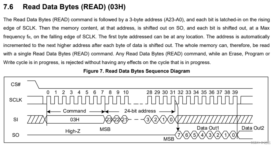
#define READ_CMD                             0x03

/**
  * @brief  Reads an amount of data from the QSPI memory.
  * @param  pData: Pointer to data to be read
  * @param  ReadAddr: Read start address
  * @param  Size: Size of data to read
  * @retval QSPI memory status
  */
uint8_t BSP_W25Qx_Read(uint8_t* pData, uint32_t ReadAddr, uint32_t Size)
{
    uint8_t cmd[4];
    uint8_t status;
    /* Configure the command */
    cmd[0] = READ_CMD;
    cmd[1] = (uint8_t)(ReadAddr > > 16);
    cmd[2] = (uint8_t)(ReadAddr > > 8);
    cmd[3] = (uint8_t)(ReadAddr);

    W25Qx_Enable();
    /* Send the read ID command */
//    HAL_SPI_Transmit(&hspi1, cmd, 4, W25Qx_TIMEOUT_VALUE);
    for(int i= 0;i< 4;i++)
        spi_SendRcvByte(SPI0,cmd[i]);
    /* Reception of the data */
//    if (HAL_SPI_Receive(&hspi1, pData,Size,W25Qx_TIMEOUT_VALUE) != HAL_OK)
//  {
//    return W25Qx_ERROR;
//  }
    for(int i= 0;i< Size;i++)
        pData[i]=spi_SendRcvByte(SPI0,0x00);
    if (status != 0x00)
  {
    return W25Qx_ERROR;
  }
    W25Qx_Disable();
    return W25Qx_OK;
}
以读取10个数据为例子,波形如下所示。
BSP_W25Qx_Read(rData2,0x1000,0x00a);

擦除扇区
最小的擦除单位是扇区,擦除指令为0x20和3字节的地址。
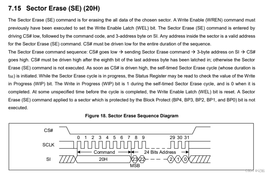
#define SECTOR_ERASE_CMD                     0x20
/**
  * @brief  Erases the specified block of the QSPI memory.
  * @param  BlockAddress: Block address to erase
  * @retval QSPI memory status
  */
uint8_t BSP_W25Qx_Erase_Block(uint32_t Address)
{
    uint8_t cmd[4];
    uint32_t tickstart=0 ;
    cmd[0] = SECTOR_ERASE_CMD;
    cmd[1] = (uint8_t)(Address > > 16);
    cmd[2] = (uint8_t)(Address > > 8);
    cmd[3] = (uint8_t)(Address);

    /* Enable write operations */
    BSP_W25Qx_WriteEnable();

    /*Select the FLASH: Chip Select low */
    W25Qx_Enable();
    /* Send the read ID command */
//    HAL_SPI_Transmit(&hspi1, cmd, 4, W25Qx_TIMEOUT_VALUE);
    for(int i =0;i< 4;i++)
        spi_SendRcvByte(SPI0,cmd[i]);
    /*Deselect the FLASH: Chip Select high */
    W25Qx_Disable();
delay_1ms(1);
    /* Wait the end of Flash writing */
    while(BSP_W25Qx_GetStatus() == W25Qx_BUSY)
    {
    tickstart++;
        /* Check for the Timeout */
    if(tickstart > W25Q128FV_SECTOR_ERASE_MAX_TIME)
    {
            return W25Qx_TIMEOUT;
    }
    }
    return W25Qx_OK;
}

写数据
对于写数据到flash中,使用0x02指令进行写数据,后面还需要指定24位地址,才能进行写数据。
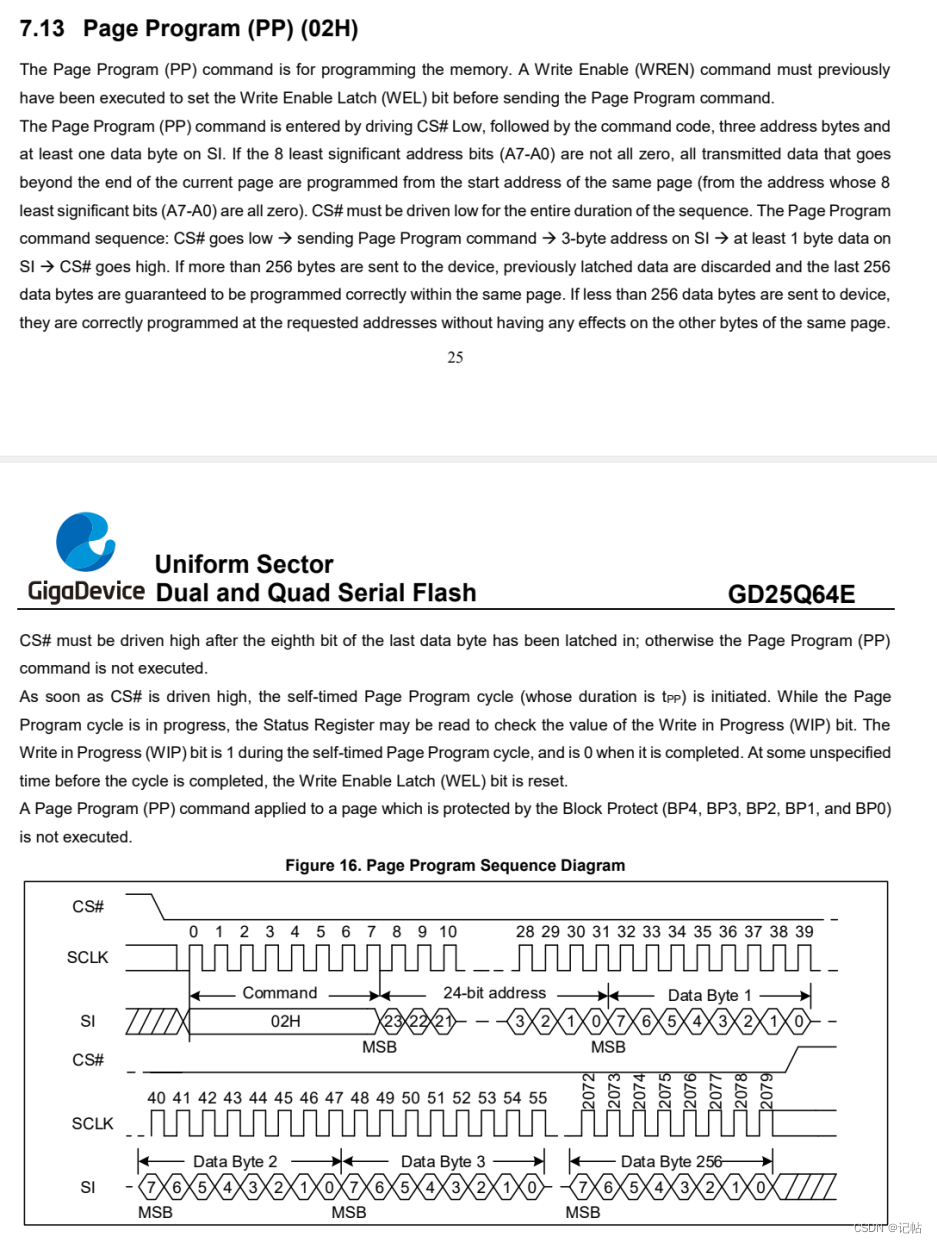
#define PAGE_PROG_CMD                        0x02
/**
  * @brief  Writes an amount of data to the QSPI memory.
  * @param  pData: Pointer to data to be written
  * @param  WriteAddr: Write start address
  * @param  Size: Size of data to write,No more than 256byte.
  * @retval QSPI memory status
  */
uint8_t BSP_W25Qx_Write(uint8_t* pData, uint32_t WriteAddr, uint32_t Size)
{
    uint8_t cmd[4];
    uint32_t end_addr, current_size, current_addr;
    uint32_t tickstart =0;

    /* Calculation of the size between the write address and the end of the page */
  current_addr = 0;

  while (current_addr <= WriteAddr)//判断地址属于哪一扇区开始
  {
    current_addr += W25Q128FV_PAGE_SIZE;//0x100- > 256 bytes
  }
  current_size = current_addr - WriteAddr;

  /* Check if the size of the data is less than the remaining place in the page */
  if (current_size > Size)
  {
    current_size = Size;
  }

  /* Initialize the adress variables *///写入地址大小范围
  current_addr = WriteAddr;
  end_addr = WriteAddr + Size;

  /* Perform the write page by page */
  do
  {
        /* Configure the command */
        cmd[0] = PAGE_PROG_CMD;
        cmd[1] = (uint8_t)(current_addr > > 16);
        cmd[2] = (uint8_t)(current_addr > > 8);
        cmd[3] = (uint8_t)(current_addr);

        /* Enable write operations */
        BSP_W25Qx_WriteEnable();

        W25Qx_Enable();
    /* Send the command */
//    if (HAL_SPI_Transmit(&hspi1,cmd, 4, W25Qx_TIMEOUT_VALUE) != HAL_OK)
//    {
//      return W25Qx_ERROR;
//    }
        for(int i=0;i< 4;i++)
            spi_SendRcvByte(SPI0,cmd[i]);

    /* Transmission of the data */
//    if (HAL_SPI_Transmit(&hspi1, pData,current_size, W25Qx_TIMEOUT_VALUE) != HAL_OK)
//    {
//      return W25Qx_ERROR;
//    }
        for(int i=0;i< current_size;i++)
            spi_SendRcvByte(SPI0,pData[i]);

            W25Qx_Disable();
        /* Wait the end of Flash writing */
        while(BSP_W25Qx_GetStatus() == W25Qx_BUSY)
        {
            tickstart++;
            /* Check for the Timeout */
            if(tickstart > W25Qx_TIMEOUT_VALUE)
            {
                return W25Qx_TIMEOUT;
            }
        }

    /* Update the address and size variables for next page programming */
    current_addr += current_size;
    pData += current_size;
    current_size = ((current_addr + W25Q128FV_PAGE_SIZE) > end_addr) ? (end_addr - current_addr) : W25Q128FV_PAGE_SIZE;
  } while (current_addr < end_addr);


    return W25Qx_OK;
}
对flash的0x1000地址进行写数据,指令如下。
BSP_W25Qx_Write(wData2,0x1000,0x000a);

keil配置
microlib 进行了高度优化以使代码变得很小。 它的功能比缺省 C 库少,并且根本不具备某些 ISO C 特性。 某些库函数的运行速度也比较慢,如果要使用printf(),必须开启。
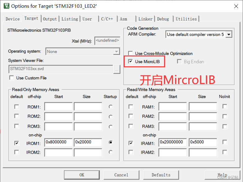
使能GPIO
void GPIO_Init(void)
{
    rcu_periph_clock_enable(RCU_GPIOA);
    rcu_periph_clock_enable(RCU_GPIOD);
    rcu_periph_clock_enable(RCU_SPI0);

    rcu_periph_clock_enable(RCU_AF);

        /* SPI0 GPIO config:SCK/PA5, MISO/PA6, MOSI/PA7 */
    gpio_init(GPIOA, GPIO_MODE_AF_PP, GPIO_OSPEED_50MHZ, GPIO_PIN_5 | GPIO_PIN_7);
    gpio_init(GPIOA, GPIO_MODE_IN_FLOATING, GPIO_OSPEED_50MHZ, GPIO_PIN_6);
    /* PD14 as NSS */
        gpio_init(GPIOD, GPIO_MODE_IPD, GPIO_OSPEED_MAX, GPIO_PIN_14);
    gpio_init(GPIOD, GPIO_MODE_OUT_PP, GPIO_OSPEED_MAX, GPIO_PIN_14);


}
SPI初始化
SPI挂载在APB2线上。
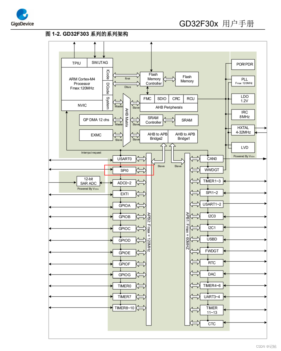
下面将SPI0分频256倍,那么速率为120M/256=468.75KHz。
void SPI_Init(void)
{
    spi_parameter_struct spi_init_struct;

    /* SPI0 parameter config */
    spi_init_struct.trans_mode           = SPI_TRANSMODE_FULLDUPLEX;//双工模式
    spi_init_struct.device_mode          = SPI_MASTER;//作为master,提供SCLK
    spi_init_struct.frame_size           = SPI_FRAMESIZE_8BIT;//8bit模式
    spi_init_struct.clock_polarity_phase = SPI_CK_PL_LOW_PH_1EDGE;//mode0
    spi_init_struct.nss                  = SPI_NSS_SOFT;
    spi_init_struct.prescale             = SPI_PSC_256;// 分频比
    spi_init_struct.endian               = SPI_ENDIAN_MSB;//高位在前
    spi_init(SPI0, &spi_init_struct);

    SET_SPI0_NSS_HIGH

        /* SPI enable */
    spi_enable(SPI0);
}
使能串口
void UART_Init(void)
{

  /* 使能GPI0A,用PA9、PA10为串口 */
    rcu_periph_clock_enable(RCU_GPIOA);

    /*使能串口0的时钟 */
    rcu_periph_clock_enable(RCU_USART0);

    /*配置USARTx_Tx(PA9)为复用推挽输出*/
    gpio_init(GPIOA, GPIO_MODE_AF_PP, GPIO_OSPEED_50MHZ, GPIO_PIN_9);

    /*配置USARTx_RxPA9)为浮空输入 */
    gpio_init(GPIOA, GPIO_MODE_IN_FLOATING, GPIO_OSPEED_50MHZ, GPIO_PIN_10);

    /* USART 配置 */
    usart_deinit(USART0);//重置串口0
    usart_baudrate_set(USART0, 115200U);//设置串口0的波特率为115200
    usart_word_length_set(USART0, USART_WL_8BIT);          // 帧数据字长
        usart_stop_bit_set(USART0, USART_STB_1BIT);               // 停止位1位
    usart_parity_config(USART0, USART_PM_NONE);           // 无奇偶校验位
    usart_receive_config(USART0, USART_RECEIVE_ENABLE);//使能接收器
    usart_transmit_config(USART0, USART_TRANSMIT_ENABLE);//使能发送器
    usart_enable(USART0);//使能USART


}
开启串口DMA接收
void UART_DMA_Init(void)
{
    dma_parameter_struct dma_init_struct;
    // 时钟开启
    rcu_periph_clock_enable(RCU_DMA0);
    /* USART0 DMA 接收配置*/
    dma_deinit(DMA0, DMA_CH4);
    dma_init_struct.direction = DMA_PERIPHERAL_TO_MEMORY;        /* 外设到内存 */
    dma_init_struct.memory_addr = (uint32_t)ReceiveBuff;            /* 设置内存接收基地址 */
    dma_init_struct.memory_inc = DMA_MEMORY_INCREASE_ENABLE;    /* 内存地址递增 */
    dma_init_struct.memory_width = DMA_MEMORY_WIDTH_8BIT;        /* 8位内存数据 */
    dma_init_struct.number = sizeof(ReceiveBuff);
    dma_init_struct.periph_addr = ((uint32_t)0x40013804);        /* 外设基地址,USART数据寄存器地址 */
    dma_init_struct.periph_inc = DMA_PERIPH_INCREASE_DISABLE;    /* 外设地址不递增 */
    dma_init_struct.periph_width = DMA_PERIPHERAL_WIDTH_8BIT;    /* 8位外设数据 */
    dma_init_struct.priority = DMA_PRIORITY_ULTRA_HIGH;            /* 最高DMA通道优先级 */
    dma_init(DMA0, DMA_CH4, &dma_init_struct);                     /* 按照结构体的配置初始化DMA */


    dma_circulation_enable(DMA0, DMA_CH4);            /* 关闭DMA循环模式 */
    dma_memory_to_memory_disable(DMA0, DMA_CH4);    /* DMA内存到内存模式不开启 */
        dma_channel_enable(DMA0, DMA_CH4);                /* 使能DMA传输 */

        usart_dma_receive_config(USART0, USART_DENR_ENABLE);    /* USART0 DMA接收模式开启 */


}
串口中断设置
void UART_nvic_Init(void)
{
    nvic_irq_enable(USART0_IRQn, 0, 0);        /* USART中断设置,抢占优先级0,子优先级0 */
    usart_interrupt_enable(USART0, USART_INT_IDLE);            /* 使能USART0空闲中断 */
}
W25Qx.c
/*********************************************************************************************************
*
* File                : ws_W25Qx.c
* Hardware Environment:
* Build Environment   : RealView MDK-ARM  Version: 4.20
* Version             : V1.0
* By                  :
*
*                                  (c) Copyright 2005-2011, WaveShare
*                                       http://www.waveshare.net
*                                          All Rights Reserved
*
*********************************************************************************************************/

#include "W25Qx.h"
#include "systick.h"


/**
  * @brief spi数据传输函数
  * @param spi_per spi外设
  * @param byte 发送字节
  * @return 接收字节
  */
uint8_t spi_SendRcvByte(uint32_t spi_per,uint8_t byte)
{
    uint8_t data;
    while(RESET == spi_i2s_flag_get(spi_per, SPI_FLAG_TBE));
    spi_i2s_data_transmit(spi_per, byte);

    while(SET == spi_i2s_flag_get(spi_per, SPI_FLAG_TRANS));
    while(RESET == spi_i2s_flag_get(spi_per, SPI_FLAG_RBNE));
    data=spi_i2s_data_receive(spi_per);
    while(SET == spi_i2s_flag_get(spi_per, SPI_FLAG_TRANS));
    return data;
}


//void spi_write_byte(uint32_t spi_periph, uint8_t data)
//{
//    while(RESET == spi_i2s_flag_get(spi_periph, SPI_FLAG_TBE));//发送缓冲区空标志
//    spi_i2s_data_transmit(spi_periph, data);

//}

//uint8_t spi_read_byte(uint32_t spi_periph)
//{
//    uint8_t read_i=0;
//    while(RESET == spi_i2s_flag_get(spi_periph, SPI_FLAG_RBNE));//接收缓冲区非空标志
//    read_i=spi_i2s_data_receive(spi_periph);
//    while(SET == spi_i2s_flag_get(spi_periph, SPI_FLAG_TRANS));
//    return read_i;
//}

/**
  * @brief  Initializes the W25Q128FV interface.
  * @retval None
  */
uint8_t BSP_W25Qx_Init(void)
{
    /* Reset W25Qxxx */
    BSP_W25Qx_Reset();

    return BSP_W25Qx_GetStatus();
}

/**
  * @brief  This function reset the W25Qx.
  * @retval None
  */
static void    BSP_W25Qx_Reset(void)
{
    uint8_t cmd[2] = {RESET_ENABLE_CMD,RESET_MEMORY_CMD};

    W25Qx_Enable();
    /* Send the reset command */


    for(int i=0;i< 2;i++){
    spi_SendRcvByte(SPI0,cmd[i]);
}


//    HAL_SPI_Transmit(&hspi1, cmd, 2, W25Qx_TIMEOUT_VALUE);
    W25Qx_Disable();

}

/**
  * @brief  Reads current status of the W25Q128FV.
  * @retval W25Q128FV memory status
  */
static uint8_t BSP_W25Qx_GetStatus(void)
{
    uint8_t cmd[] = {READ_STATUS_REG1_CMD};
    uint8_t status;

    W25Qx_Enable();
    /* Send the read status command */
//    spi_write_byte(SPI0, cmd[0]);
    //HAL_SPI_Transmit(&hspi1, cmd, 1, W25Qx_TIMEOUT_VALUE);
    /* Reception of the data */
//    status=spi_read_byte(SPI0);
    //HAL_SPI_Receive(&hspi1,&status, 1, W25Qx_TIMEOUT_VALUE);


    spi_SendRcvByte(SPI0,cmd[0]);
    status=spi_SendRcvByte(SPI0,0x00);


    W25Qx_Disable();

    /* Check the value of the register */
  if((status & W25Q128FV_FSR_BUSY) != 0)
  {
    return W25Qx_BUSY;
  }
    else
    {
        return W25Qx_OK;
    }
}

/**
  * @brief  This function send a Write Enable and wait it is effective.
  * @retval None
  */
uint8_t BSP_W25Qx_WriteEnable(void)
{
    uint8_t cmd[] = {WRITE_ENABLE_CMD};
//    uint32_t tickstart = HAL_GetTick();
uint32_t tickstart=0;
    /*Select the FLASH: Chip Select low */
    W25Qx_Enable();
    /* Send the read ID command */
//    HAL_SPI_Transmit(&hspi1, cmd, 1, W25Qx_TIMEOUT_VALUE);
    spi_SendRcvByte(SPI0,cmd[0]);
    /*Deselect the FLASH: Chip Select high */
    W25Qx_Disable();

    /* Wait the end of Flash writing */
    while(BSP_W25Qx_GetStatus() == W25Qx_BUSY)
    {
        tickstart++;
        /* Check for the Timeout */
    if(tickstart > W25Qx_TIMEOUT_VALUE)
    {
            return W25Qx_TIMEOUT;
    }
    }

    return W25Qx_OK;
}

/**
  * @brief  Read Manufacture/Device ID.
    * @param  return value address
  * @retval None
  */
void BSP_W25Qx_Read_ID(uint8_t *ID)
{
    uint8_t cmd[4] = {READ_ID_CMD,0x00,0x00,0x00};

    W25Qx_Enable();
    /* Send the read ID command */


//    HAL_SPI_Transmit(&hspi1, cmd, 4, W25Qx_TIMEOUT_VALUE);
    /* Reception of the data */
//    HAL_SPI_Receive(&hspi1,ID, 2, W25Qx_TIMEOUT_VALUE);


    for(int i=0;i< 4;i++)
        spi_SendRcvByte(SPI0,cmd[i]);

    for(int i=0;i< 2;i++)
    {

        ID[i]=spi_SendRcvByte(SPI0,0x00);
}

    W25Qx_Disable();

}

/**
  * @brief  Reads an amount of data from the QSPI memory.
  * @param  pData: Pointer to data to be read
  * @param  ReadAddr: Read start address
  * @param  Size: Size of data to read
  * @retval QSPI memory status
  */
uint8_t BSP_W25Qx_Read(uint8_t* pData, uint32_t ReadAddr, uint32_t Size)
{
    uint8_t cmd[4];
    uint8_t status;
    /* Configure the command */
    cmd[0] = READ_CMD;
    cmd[1] = (uint8_t)(ReadAddr > > 16);
    cmd[2] = (uint8_t)(ReadAddr > > 8);
    cmd[3] = (uint8_t)(ReadAddr);

    W25Qx_Enable();
    /* Send the read ID command */
//    HAL_SPI_Transmit(&hspi1, cmd, 4, W25Qx_TIMEOUT_VALUE);
    for(int i= 0;i< 4;i++)
        spi_SendRcvByte(SPI0,cmd[i]);
    /* Reception of the data */
//    if (HAL_SPI_Receive(&hspi1, pData,Size,W25Qx_TIMEOUT_VALUE) != HAL_OK)
//  {
//    return W25Qx_ERROR;
//  }
    for(int i= 0;i< Size;i++)
        pData[i]=spi_SendRcvByte(SPI0,0x00);
    if (status != 0x00)
  {
    return W25Qx_ERROR;
  }
    W25Qx_Disable();
    return W25Qx_OK;
}

/**
  * @brief  Writes an amount of data to the QSPI memory.
  * @param  pData: Pointer to data to be written
  * @param  WriteAddr: Write start address
  * @param  Size: Size of data to write,No more than 256byte.
  * @retval QSPI memory status
  */
uint8_t BSP_W25Qx_Write(uint8_t* pData, uint32_t WriteAddr, uint32_t Size)
{
    uint8_t cmd[4];
    uint32_t end_addr, current_size, current_addr;
    uint32_t tickstart =0;

    /* Calculation of the size between the write address and the end of the page */
  current_addr = 0;

  while (current_addr <= WriteAddr)//判断地址属于哪一扇区开始
  {
    current_addr += W25Q128FV_PAGE_SIZE;//0x100- > 256 bytes
  }
  current_size = current_addr - WriteAddr;

  /* Check if the size of the data is less than the remaining place in the page */
  if (current_size > Size)
  {
    current_size = Size;
  }

  /* Initialize the adress variables *///写入地址大小范围
  current_addr = WriteAddr;
  end_addr = WriteAddr + Size;

  /* Perform the write page by page */
  do
  {
        /* Configure the command */
        cmd[0] = PAGE_PROG_CMD;
        cmd[1] = (uint8_t)(current_addr > > 16);
        cmd[2] = (uint8_t)(current_addr > > 8);
        cmd[3] = (uint8_t)(current_addr);

        /* Enable write operations */
        BSP_W25Qx_WriteEnable();

        W25Qx_Enable();
    /* Send the command */
//    if (HAL_SPI_Transmit(&hspi1,cmd, 4, W25Qx_TIMEOUT_VALUE) != HAL_OK)
//    {
//      return W25Qx_ERROR;
//    }
        for(int i=0;i< 4;i++)
            spi_SendRcvByte(SPI0,cmd[i]);

    /* Transmission of the data */
//    if (HAL_SPI_Transmit(&hspi1, pData,current_size, W25Qx_TIMEOUT_VALUE) != HAL_OK)
//    {
//      return W25Qx_ERROR;
//    }
        for(int i=0;i< current_size;i++)
            spi_SendRcvByte(SPI0,pData[i]);

            W25Qx_Disable();
        /* Wait the end of Flash writing */
        while(BSP_W25Qx_GetStatus() == W25Qx_BUSY)
        {
            tickstart++;
            /* Check for the Timeout */
            if(tickstart > W25Qx_TIMEOUT_VALUE)
            {
                return W25Qx_TIMEOUT;
            }
        }

    /* Update the address and size variables for next page programming */
    current_addr += current_size;
    pData += current_size;
    current_size = ((current_addr + W25Q128FV_PAGE_SIZE) > end_addr) ? (end_addr - current_addr) : W25Q128FV_PAGE_SIZE;
  } while (current_addr < end_addr);


    return W25Qx_OK;
}

/**
  * @brief  Erases the specified block of the QSPI memory.
  * @param  BlockAddress: Block address to erase
  * @retval QSPI memory status
  */
uint8_t BSP_W25Qx_Erase_Block(uint32_t Address)
{
    uint8_t cmd[4];
    uint32_t tickstart=0 ;
    cmd[0] = SECTOR_ERASE_CMD;
    cmd[1] = (uint8_t)(Address > > 16);
    cmd[2] = (uint8_t)(Address > > 8);
    cmd[3] = (uint8_t)(Address);

    /* Enable write operations */
    BSP_W25Qx_WriteEnable();

    /*Select the FLASH: Chip Select low */
    W25Qx_Enable();
    /* Send the read ID command */
//    HAL_SPI_Transmit(&hspi1, cmd, 4, W25Qx_TIMEOUT_VALUE);
    for(int i =0;i< 4;i++)
        spi_SendRcvByte(SPI0,cmd[i]);
    /*Deselect the FLASH: Chip Select high */
    W25Qx_Disable();
delay_1ms(1);
    /* Wait the end of Flash writing */
    while(BSP_W25Qx_GetStatus() == W25Qx_BUSY)
    {
    tickstart++;
        /* Check for the Timeout */
    if(tickstart > W25Q128FV_SECTOR_ERASE_MAX_TIME)
    {
            return W25Qx_TIMEOUT;
    }
    }
    return W25Qx_OK;
}

/**
  * @brief  Erases the entire QSPI memory.This function will take a very long time.
  * @retval QSPI memory status
  */
uint8_t BSP_W25Qx_Erase_Chip(void)
{
    uint8_t cmd[4];
    uint32_t tickstart ;
    cmd[0] = SECTOR_ERASE_CMD;

    /* Enable write operations */
    BSP_W25Qx_WriteEnable();

    /*Select the FLASH: Chip Select low */
    W25Qx_Enable();
    /* Send the read ID command */
//    HAL_SPI_Transmit(&hspi1, cmd, 1, W25Qx_TIMEOUT_VALUE);
    spi_SendRcvByte(SPI0,cmd[0]);
    /*Deselect the FLASH: Chip Select high */
    W25Qx_Disable();

    /* Wait the end of Flash writing */
    while(BSP_W25Qx_GetStatus() != W25Qx_BUSY)
    {
        tickstart++;
        /* Check for the Timeout */
    if(tickstart > W25Q128FV_BULK_ERASE_MAX_TIME)
    {
            return W25Qx_TIMEOUT;
    }
    }
    return W25Qx_OK;
}
W25Qx.h
/*********************************************************************************************************
*
* File                : W25Qx.h
* Hardware Environment:
* Build Environment   : RealView MDK-ARM  Version: 5.15
* Version             : V1.0
* By                  :
*
*                                  (c) Copyright 2005-2015, WaveShare
*                                       http://www.waveshare.net
*                                          All Rights Reserved
*
*********************************************************************************************************/
/* Define to prevent recursive inclusion -------------------------------------*/
#ifndef __W25Qx_H
#define __W25Qx_H

#ifdef __cplusplus
 extern "C" {
#endif

/* Includes ------------------------------------------------------------------*/
#include "gd32f30x.h"
#include "gd32f30x_spi.h"

/** @addtogroup BSP
  * @{
  */

/** @addtogroup Components
  * @{
  */

/** @addtogroup W25Q128FV
  * @{
  */

/** @defgroup W25Q128FV_Exported_Types
  * @{
  */

/**
  * @}
  */

/** @defgroup W25Q128FV_Exported_Constants
  * @{
  */

/**
  * @brief  W25Q128FV Configuration
  */
#define W25Q128FV_FLASH_SIZE                  0x1000000 /* 128 MBits = > 16MBytes */
#define W25Q128FV_SECTOR_SIZE                 0x10000   /* 256 sectors of 64KBytes */
#define W25Q128FV_SUBSECTOR_SIZE              0x1000    /* 4096 subsectors of 4kBytes */
#define W25Q128FV_PAGE_SIZE                   0x100     /* 65536 pages of 256 bytes */

#define W25Q128FV_DUMMY_CYCLES_READ           4
#define W25Q128FV_DUMMY_CYCLES_READ_QUAD      10

#define W25Q128FV_BULK_ERASE_MAX_TIME         250000
#define W25Q128FV_SECTOR_ERASE_MAX_TIME       10000
#define W25Q128FV_SUBSECTOR_ERASE_MAX_TIME    800
#define W25Qx_TIMEOUT_VALUE 1000

/**
  * @brief  W25Q128FV Commands
  */
/* Reset Operations */
#define RESET_ENABLE_CMD                     0x66
#define RESET_MEMORY_CMD                     0x99

#define ENTER_QPI_MODE_CMD                   0x38
#define EXIT_QPI_MODE_CMD                    0xFF

/* Identification Operations */
#define READ_ID_CMD                          0x90
#define DUAL_READ_ID_CMD                     0x92
#define QUAD_READ_ID_CMD                     0x94
#define READ_JEDEC_ID_CMD                    0x9F

/* Read Operations */
#define READ_CMD                             0x03
#define FAST_READ_CMD                        0x0B
#define DUAL_OUT_FAST_READ_CMD               0x3B
#define DUAL_INOUT_FAST_READ_CMD             0xBB
#define QUAD_OUT_FAST_READ_CMD               0x6B
#define QUAD_INOUT_FAST_READ_CMD             0xEB

/* Write Operations */
#define WRITE_ENABLE_CMD                     0x06
#define WRITE_DISABLE_CMD                    0x04

/* Register Operations */
#define READ_STATUS_REG1_CMD                  0x05
#define READ_STATUS_REG2_CMD                  0x35
#define READ_STATUS_REG3_CMD                  0x15

#define WRITE_STATUS_REG1_CMD                 0x01
#define WRITE_STATUS_REG2_CMD                 0x31
#define WRITE_STATUS_REG3_CMD                 0x11


/* Program Operations */
#define PAGE_PROG_CMD                        0x02
#define QUAD_INPUT_PAGE_PROG_CMD             0x32


/* Erase Operations */
#define SECTOR_ERASE_CMD                     0x20
#define CHIP_ERASE_CMD                       0xC7

#define PROG_ERASE_RESUME_CMD                0x7A
#define PROG_ERASE_SUSPEND_CMD               0x75


/* Flag Status Register */
#define W25Q128FV_FSR_BUSY                    ((uint8_t)0x01)    /*!< busy */
#define W25Q128FV_FSR_WREN                    ((uint8_t)0x02)    /*!< write enable */
#define W25Q128FV_FSR_QE                      ((uint8_t)0x02)    /*!< quad enable */


#define W25Qx_Enable()             gpio_bit_reset(GPIOD,GPIO_PIN_14)
#define W25Qx_Disable()         gpio_bit_set(GPIOD,GPIO_PIN_14)

#define W25Qx_OK            ((uint8_t)0x00)
#define W25Qx_ERROR         ((uint8_t)0x01)
#define W25Qx_BUSY          ((uint8_t)0x02)
#define W25Qx_TIMEOUT                ((uint8_t)0x03)


uint8_t BSP_W25Qx_Init(void);
static void    BSP_W25Qx_Reset(void);
static uint8_t BSP_W25Qx_GetStatus(void);
uint8_t BSP_W25Qx_WriteEnable(void);
void BSP_W25Qx_Read_ID(uint8_t *ID);
uint8_t BSP_W25Qx_Read(uint8_t* pData, uint32_t ReadAddr, uint32_t Size);
uint8_t BSP_W25Qx_Write(uint8_t* pData, uint32_t WriteAddr, uint32_t Size);
uint8_t BSP_W25Qx_Erase_Block(uint32_t Address);
uint8_t BSP_W25Qx_Erase_Chip(void);

/**
  * @}
  */

/** @defgroup W25Q128FV_Exported_Functions
  * @{
  */
/**
  * @}
  */

/**
  * @}
  */

/**
  * @}
  */

/**
  * @}
  */

#ifdef __cplusplus
}
#endif

#endif /* __W25Qx_H */
案例
向0扇区(0块0扇区),17扇区(1块1扇区),34扇区(2块2扇区)分别写入0x200的数据。
头文件定义
/* USER CODE BEGIN Includes */
#include "stdio.h"

#include "W25Qx.h"
/* USER CODE END Includes */
串口接收和flash数组定义
#define SET_SPI0_NSS_HIGH          gpio_bit_set(GPIOD,GPIO_PIN_14);
#define SET_SPI0_NSS_LOW           gpio_bit_reset(GPIOD,GPIO_PIN_14);


#define BUFFERSIZE 255           //可以接收的最大字符个数
uint8_t ReceiveBuff[BUFFERSIZE]; //接收缓冲区
uint8_t recv_end_flag = 0,Rx_len;//接收完成中断标志,接收到字符长度

uint8_t wData1[0x200];
uint8_t wData2[0x200];
uint8_t wData3[0x200];

uint8_t rData1[0x200];
uint8_t rData2[0x200];
uint8_t rData3[0x200];
uint8_t ID[4];
uint32_t i;

uint8_t flag[1] ;
int i_flag = 0;
void uart_data(void);
串口重定向
/* retarget the C library printf function to the USART */
int fputc(int ch, FILE *f)
{
    usart_data_transmit(USART0, (uint8_t)ch);
    while(RESET == usart_flag_get(USART0, USART_FLAG_TBE));

    return ch;
}
串口中断设置
/* 串口0中断服务程序 */
void USART0_IRQHandler(void)
{
    if(RESET != usart_interrupt_flag_get(USART0, USART_INT_FLAG_IDLE)) //空闲中断
    {
        usart_interrupt_flag_clear(USART0,USART_INT_FLAG_IDLE);    /* 清除空闲中断标志位 */
        usart_data_receive(USART0);                                /* 清除接收完成标志位 */
        dma_channel_disable(DMA0, DMA_CH4);                        /* 关闭DMA传输 */
        uint32_t temp;
        temp  = dma_transfer_number_get(DMA0,DMA_CH4);//获取DMA当前还有多少未填充
    Rx_len =  BUFFERSIZE - temp; //计算串口接收到的数据个数
    recv_end_flag = 1;


//        USART_RX_NUM = sizeof(dma_buffer) - dma_transfer_number_get(DMA0,DMA_CH4);
//        printf("RECV %d date:%srn", USART_RX_NUM, dma_buffer);
//        memset(&dma_buffer ,'�',sizeof(dma_buffer));
//        /* 重新设置DMA传输 */
//        dma_memory_address_config(DMA0,DMA_CH4,(uint32_t)dma_buffer);
//        dma_transfer_number_config(DMA0,DMA_CH4,sizeof(dma_buffer));
//        dma_channel_enable(DMA0, DMA_CH4);        /* 开启DMA传输 */
    }
}
主程序
读取ID和flash数据及擦除。
printf("GD Nor Flash案例n");
/*##-1- Read the device ID ########################*/
BSP_W25Qx_Init();//鍒濆鍖朩25Q64
BSP_W25Qx_Read_ID(ID);//璇诲彇ID
//get_DeviceId();
if((ID[0] != 0xC8) | (ID[1] != 0x16))
{
printf("error");
while(1);
// Error_Handler();//濡傛灉 ID涓嶅鎵撳嵃閿欒
}
else//ID姝g‘锛屾墦鍗癐D
{
printf("W25Q64 ID : ");
for(i=0;i< 2;i++)
{
printf("0x%02X ",ID[i]);
}
printf("rnrn");
}
/**************************读取第0扇区数据**************************************************************/
/*##-3- Read the flash ########################*/
/*读取数据,rData读取数据的指针,起始地址0x00,读取数据长度0x200*/
if(BSP_W25Qx_Read(rData1,0x0,0x200)== W25Qx_OK)
printf("读取原始的0个扇区数据成功!n");
else
{
printf("error");
while(1);
}
/*打印数据*/
printf("读取原始的0个扇区数据为: rn");
for(i =0;i< 0x200;i++)
{
if(i%20==0)
printf("n0扇区第%d到%d的数据为:rn",i,i+19);
printf("0x%02X ",rData1[i]);
}
printf("n");
/**************************读取第17扇区数据**************************************************************/
/*##-3- Read the flash ########################*/
/*读取数据,rData读取数据的指针,起始地址0x1000,读取数据长度0x200*/
if(BSP_W25Qx_Read(rData2,0x11000,0x200)== W25Qx_OK)
printf("读取原始的17个扇区数据成功!n");
else
{
printf("error");
while(1);
}
/*打印数据*/
printf("读取原始的2个扇区数据为:");
for(i =0;i< 0x200;i++)
{
if(i%20==0)
printf("n17扇区第%d到%d的数据为:rn",i,i+19);
printf("0x%02X ",rData2[i]);
}
printf("n");
/**************************读取第34扇区数据**************************************************************/
/*##-3- Read the flash ########################*/
/*读取数据,rData读取数据的指针,起始地址0x2000,读取数据长度0x200*/
if(BSP_W25Qx_Read(rData3,0x22000,0x200)== W25Qx_OK)
printf("读取原始的34个扇区数据成功!n");
else
{
printf("error");
while(1);
}
/*打印数据*/
printf("读取原始的34个扇区数据为: ");
for(i =0;i< 0x200;i++)
{
if(i%20==0)
printf("n34扇区第%d到%d的数据为:rn",i,i+19);
printf("0x%02X ",rData3[i]);
}
printf("n");
/**************************清除第0扇区数据为0**************************************************************/
/*##-2- Erase Block ##################################*/
if(BSP_W25Qx_Erase_Block(0) == W25Qx_OK)
printf(" QSPI Erase Block okrn");
else
{
printf("error");
while(1);
}
/*##-2- Written to the flash ########################*/
/* fill buffer */
printf(" 初始化数据,清零第0扇区前0x200的数据!rn");
for(i =0;i< 0x200;i ++)
{
wData1[i] = 0;
rData1[i] = 0;
}
/*写入数据,wData写入数据的指针,起始地址0x00,写入数据长度0x200*/
if(BSP_W25Qx_Write(wData1,0x00,0x200)== W25Qx_OK)
printf("清零第0扇区前0x200的数据成功!rn");
else
{
printf("error");
while(1);
}
/*##-3- Read the flash ########################*/
/*读取数据,rData读取数据的指针,起始地址0x00,读取数据长度0x200*/
if(BSP_W25Qx_Read(rData1,0x00,0x200)== W25Qx_OK)
printf("读取第0扇区前0x200数据成功!rnrn");
else
{
printf("error");
while(1);
}
/*打印数据*/
printf("读取第0扇区前0x200数据为: rn");
for(i =0;i< 0x200;i++)
{
if(i%20==0)
printf("n第%d到%d的数据为:rn",i,i+19);
printf("0x%02X ",rData1[i]);
}
printf("n");
/**************************清除第17扇区数据为0**************************************************************/
/*##-2- Erase Block ##################################*/
if(BSP_W25Qx_Erase_Block(0x11000) == W25Qx_OK)
printf(" QSPI Erase Block okrn");
else
{
printf("error");
while(1);
}
/*##-2- Written to the flash ########################*/
/* fill buffer */
printf(" 初始化数据,清零第17扇区前0x200的数据!rn");
for(i =0;i< 0x200;i ++)
{
wData2[i] = 0;
rData2[i] = 0;
}
/*写入数据,wData写入数据的指针,起始地址0x1000,写入数据长度0x200*/
if(BSP_W25Qx_Write(wData2,0x11000,0x200)== W25Qx_OK)
printf("清零第2扇区前0x200的数据成功!rn");
else
{
printf("error");
while(1);
}
/*##-3- Read the flash ########################*/
/*读取数据,rData读取数据的指针,起始地址0x00,读取数据长度0x200*/
if(BSP_W25Qx_Read(rData2,0x11000,0x200)== W25Qx_OK)
printf("读取第17扇区前0x200数据成功!rnrn");
else
{
printf("error");
while(1);
}
/*打印数据*/
printf("读取第17扇区前0x200数据为: rn");
for(i =0;i< 0x200;i++)
{
if(i%20==0)
printf("n第%d到%d的数据为:rn",i,i+19);
printf("0x%02X ",rData2[i]);
}
printf("n");
/**************************清除第34扇区数据为0**************************************************************/
/*##-2- Erase Block ##################################*/
if(BSP_W25Qx_Erase_Block(0x22000) == W25Qx_OK)
printf(" QSPI Erase Block okrn");
else
{
printf("error");
while(1);
}
/*##-2- Written to the flash ########################*/
/* fill buffer */
printf(" 初始化数据,清零第34扇区前0x200的数据!rn");
for(i =0;i< 0x200;i ++)
{
wData3[i] = 0;
rData3[i] = 0;
}
/*写入数据,wData写入数据的指针,起始地址0x22000,写入数据长度0x200*/
if(BSP_W25Qx_Write(wData3,0x22000,0x200)== W25Qx_OK)
printf("清零第34扇区前0x200的数据成功!rn");
else
{
printf("error");
while(1);
}
/*##-3- Read the flash ########################*/
/*读取数据,rData读取数据的指针,起始地址0x00,读取数据长度0x200*/
if(BSP_W25Qx_Read(rData3,0x22000,0x200)== W25Qx_OK)
printf("读取第34扇区前0x200数据成功!rnrn");
else
{
printf("error");
while(1);
}
/*打印数据*/
printf("读取第34扇区前0x200数据为: rn");
for(i =0;i< 0x200;i++)
{
if(i%20==0)
printf("n第%d到%d的数据为:rn",i,i+19);
printf("0x%02X ",rData3[i]);
}
printf("n");
主程序。
while (1){
        uart_data();
        delay_1ms(10);
    }
数据处理
void uart_data(void)
{
    if(recv_end_flag ==1)//接收完成标志
    {


if(ReceiveBuff[0]==0x00)
        {
            printf("写入数据长度:%dn",Rx_len-2);
            for(int i =0;i< Rx_len-2;i++)
            {
                wData1[ (i+ReceiveBuff[1]) ] = ReceiveBuff[i+2];

            }


        /*##-2- Erase Block ##################################*/
        if(BSP_W25Qx_Erase_Block(0) == W25Qx_OK)
            printf(" QSPI Erase Block okrn");
        else
    {
        printf("error");
        while(1);
    }


        /*写入数据,wData写入数据的指针,起始地址0x00,写入数据长度0x200*/
        if(BSP_W25Qx_Write(wData1,0x00,0x200)== W25Qx_OK)

            printf("扇区0数据成功~~~~~~~~~~~~~~~~~~~~~~~~~~!rn");
        else
    {
        printf("error");
        while(1);
    }

        if(BSP_W25Qx_Read(rData1,0x00,0x200)== W25Qx_OK)
            printf("读取扇区0前0x200数据成功!rnrn");
        else
    {
        printf("error");
        while(1);
    }
        /*打印数据*/
        printf("读取扇区0前0x200数据为: rn");

        for(i =0;i< 0x200;i++)
        {
            if(i%20==0)
                printf("n第%d到%d的数据为:rn",i,i+19);
                    printf("0x%02X  ",wData1[i]);
        }

        printf("n");

    }


    else if(ReceiveBuff[0]==0x17)
    {
            printf("写入数据长度:%dn",Rx_len-2);
            for(int i =0;i< Rx_len-2;i++)
            {
//                Data[i]=ReceiveBuff[i+2];
                wData2[ (i+ReceiveBuff[1]) ] = ReceiveBuff[i+2];
            }


        /*##-17- Erase Block ##################################*/
        if(BSP_W25Qx_Erase_Block(0x11000) == W25Qx_OK)
            printf(" QSPI Erase Block okrn");
        else
    {
        printf("error");
        while(1);
    }


        /*写入数据,wData写入数据的指针,起始地址0x11000,写入数据长度0x200*/
        if(BSP_W25Qx_Write(wData2,0x11000,0x200)== W25Qx_OK)

            printf("扇区17数据成功~~~~~~~~~~~~~~~~~~~~~~~~~~!rn");
        else
    {
        printf("error");
        while(1);
    }

        if(BSP_W25Qx_Read(rData2,0x11000,0x200)== W25Qx_OK)
            printf("读取扇区17前0x200数据成功!rnrn");
        else
    {
        printf("error");
        while(1);
    }
        /*打印数据*/
        printf("读取扇区17前0x200数据为: rn");

        for(i =0;i< 0x200;i++)
        {
            if(i%20==0)
                printf("n第%d到%d的数据为:rn",i,i+19);
                    printf("0x%02X  ",rData2[i]);
        }

        printf("n");

    }


    else if(ReceiveBuff[0]==0x34)
    {
            printf("写入数据长度:%dn",Rx_len-2);
            for(int i =0;i< Rx_len-2;i++)
            {
//                Data[i]=ReceiveBuff[i+2];
                wData3[ (i+ReceiveBuff[1]) ] = ReceiveBuff[i+2];
            }


        /*##-22- Erase Block ##################################*/
        if(BSP_W25Qx_Erase_Block(0x22000) == W25Qx_OK)
            printf(" QSPI Erase Block okrn");
        else
    {
        printf("error");
        while(1);
    }


        /*写入数据,wData写入数据的指针,起始地址0x22000,写入数据长度0x200*/
        if(BSP_W25Qx_Write(wData3,0x22000,0x200)== W25Qx_OK)

            printf("扇区34数据成功~~~~~~~~~~~~~~~~~~~~~~~~~~!rn");
        else
    {
        printf("error");
        while(1);
    }

        if(BSP_W25Qx_Read(rData3,0x22000,0x200)== W25Qx_OK)
            printf("读取扇区34前0x200数据成功!rnrn");
        else
    {
        printf("error");
        while(1);
    }
        /*打印数据*/
        printf("读取扇区34前0x200数据为: rn");

        for(i =0;i< 0x200;i++)
        {
            if(i%20==0)
                printf("n第%d到%d的数据为:rn",i,i+19);
                    printf("0x%02X  ",rData3[i]);
        }

        printf("n");

    }


        else
            printf("输入错误!");

    for(int i = 0; i < Rx_len ; i++) //清空接收缓存区
    ReceiveBuff[i]=0;//置0
    Rx_len=0;//接收数据长度清零
    recv_end_flag=0;//接收标志位清零
        //开启下一次接收
        memset(&ReceiveBuff ,'�',sizeof(ReceiveBuff));
        /* 重新设置DMA传输 */
        dma_memory_address_config(DMA0,DMA_CH4,(uint32_t)ReceiveBuff);
        dma_transfer_number_config(DMA0,DMA_CH4,sizeof(ReceiveBuff));
        dma_channel_enable(DMA0, DMA_CH4);        /* 开启DMA传输 */
    }

}
演示
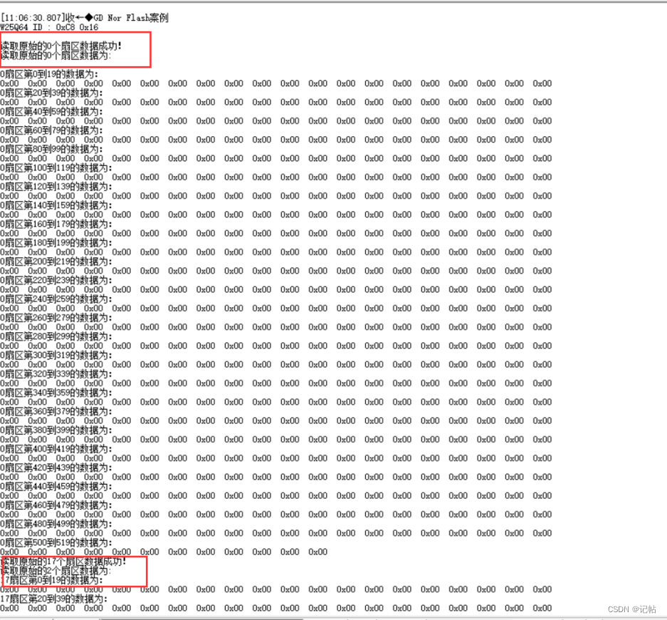
W25Q64芯片型号的ID为0XEF17,下方读取为0XC816,所以读取成功。

开机会打印出0,17,34扇区的前0x200个数据。
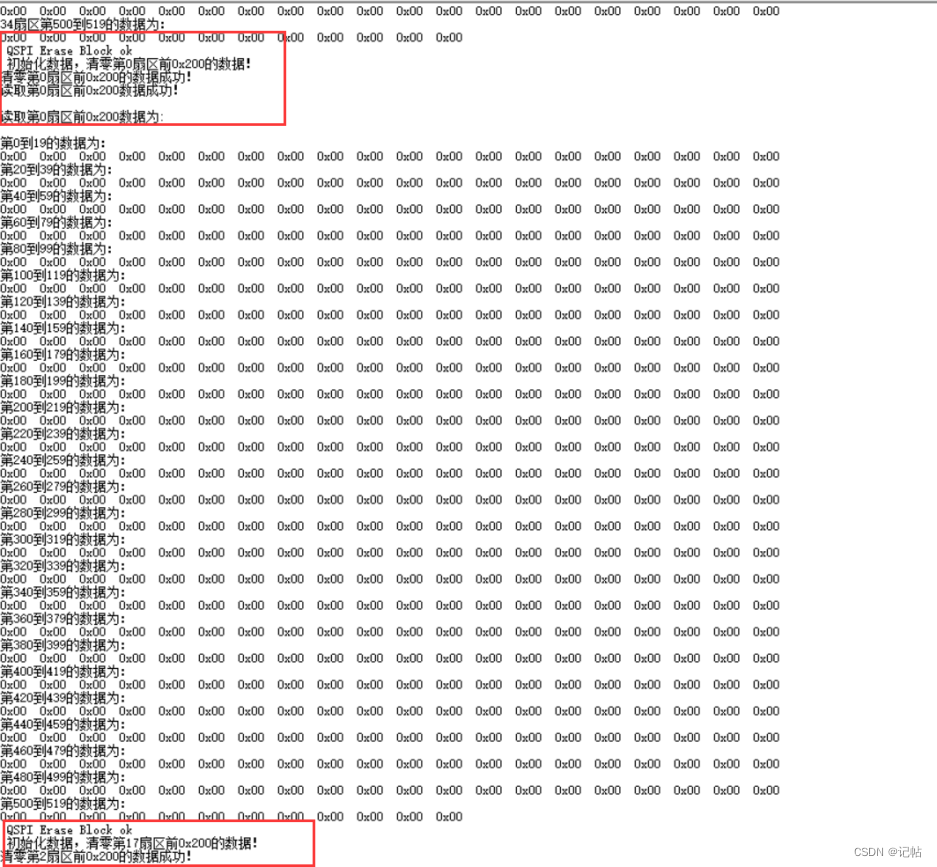
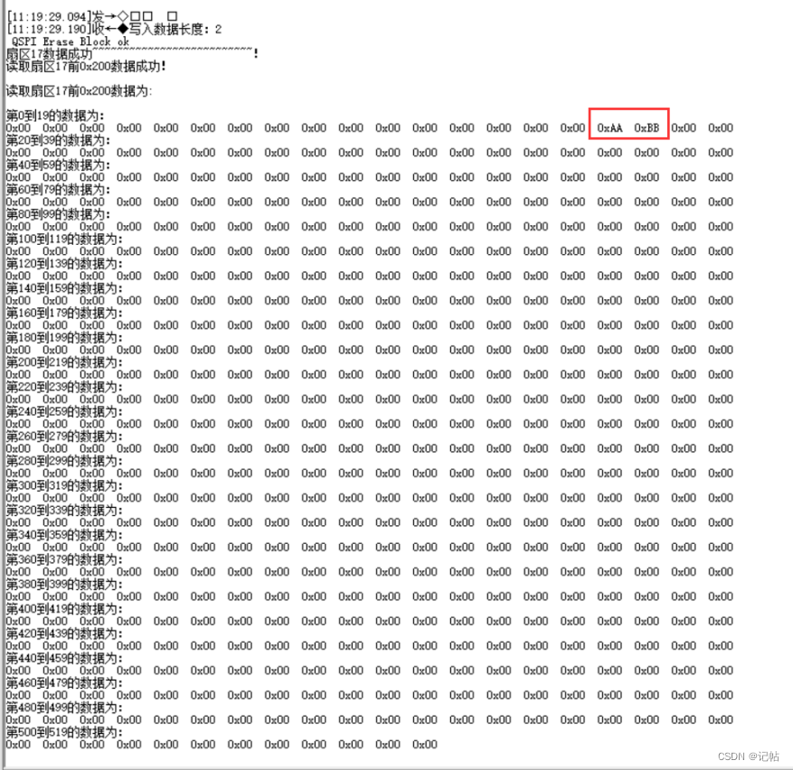
打印完原始数据之后将数据全部清零,清零完成如下图所示。
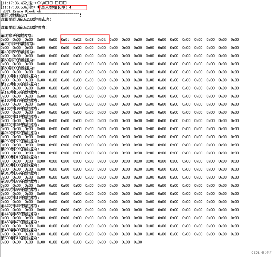
串口定义了ReceiveBuff[0]的数据为写入什么扇区,ReceiveBuff[0]为1写入扇区1,ReceiveBuff[0]为2写入扇区2,ReceiveBuff[0]为3写入扇区3,若为其他数据,则打印输入错误;ReceiveBuff[1]则为写入的位置。 输入:00 05 01 02 03 04 向扇区0的的05号位置开始写入数据01 02 03 04。
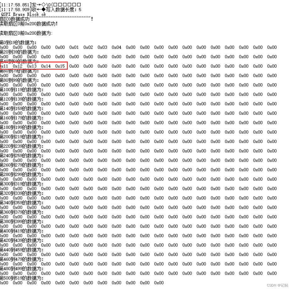
输入:00 28 11 12 13 14 15 向扇区0的的40(28是十六进制)号位置开始写入数据11 12 13 14 15。
输入:17 10 aa bb 向扇区17的的16(10是十六进制)号位置开始写入数据aa bb。
审核编辑 黄宇
-
芯片
+关注
关注
455文章
50784浏览量
423450 -
SPI
+关注
关注
17文章
1706浏览量
91555 -
固件库
+关注
关注
2文章
97浏览量
14939
发布评论请先 登录
相关推荐
【GD32F303】星空派介绍
兆易创新SPI NOR Flash GD25LX256E喜获“中国芯”奖项
兆易创新:基于GD SPI NOR Flash的TWS耳机方案
STM32CUBEMX开发GD32F303(16)----移植兆易创新SPI Nor Flash之GD25Q64Flash

STM32CUBEMX开发GD32F303(17)----内部Flash读写

GD32F303固件库开发(17)----内部Flash读写
【GD32F303红枫派开发板使用手册】第二十讲 SPI-SPI NAND FLASH读写实验
【GD32 MCU 移植教程】2、从 GD32F303 移植到 GD32F503


 GD32F303固件库开发(16)----移植兆易创新SPI Nor Flash之GD25Q64Flash



评论