 瑞萨e2studio----定时器GPT配置输入捕获

1.概述
本篇文章主要介绍如何使用e2studio对瑞萨单片机定时器输入捕获,同时输入一个PWM验证是否正确。
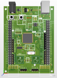
2.硬件准备
首先需要准备一个开发板,这里我准备的是芯片型号 R7FA2L1AB2DFL 的开发板。
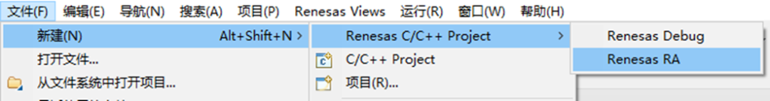
3.新建工程
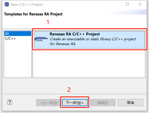
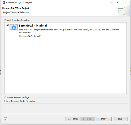
4.工程模板
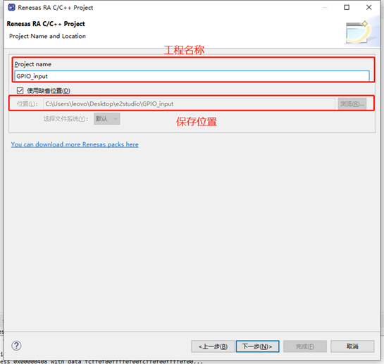
5.保存工程路径
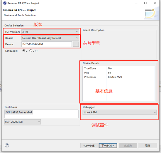
6.芯片配置
本文中使用R7FA2L1AB2DFL来进行演示。
7
7.工程模板选择
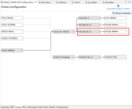
8.选择定时器
时钟源在这设置的是PCKLD 48M 。
可以通过修改该频率来修改占空比频率。
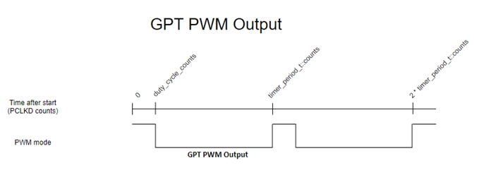
9.PWM(脉冲宽度调制)
脉冲宽度调制是一种interwetten与威廉的赔率体系 控制方式,根据相应载荷的变化来调制晶体管基极或MOS管栅极的偏置,来实现晶体管或MOS管导通时间的改变,从而实现开关稳压电源输出的改变。这种方式能使电源的输出电压在工作条件变化时保持恒定,是利用微处理器的数字信号对模拟电路进行控制的一种非常有效的威廉希尔官方网站 。脉冲宽度调制是利用微处理器的数字输出来对模拟电路进行控制的一种非常有效的威廉希尔官方网站 ,广泛应用在从测量、通信到功率控制与变换的许多领域中。
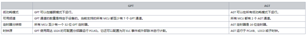
在瑞萨RA系列MCU中有两种定时器,一种是通用PWM定时器GPT,另外一种是异步通用定时器AGT。
频率=主频/period
+占空比=cycle/period
10.定时器配置
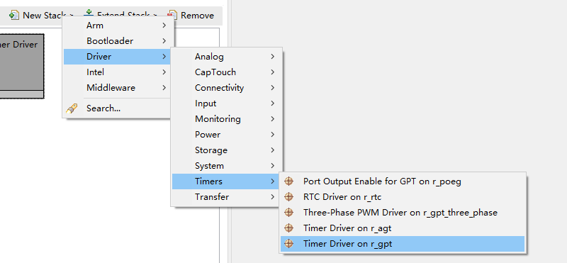
点击Stacks->New Stack->Driver->Timers->Timer Driver on r_gpt。
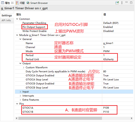
11.定时器输出PWM配置
设置PWM输出,输出频率为1kHz,占空比为80%。
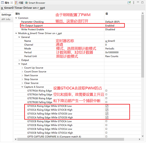
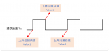
12.定时器输入捕获配置
点击Stacks->New Stack->Driver->Timers->Timer Driver on r_gpt。
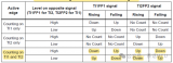
设置定时器输入捕获,由于需要读取PWM的占空比和频率,故需要设置上升沿和下降沿都产生一个捕获中断。
13.设置e2studio堆栈

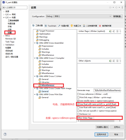
14.e2studio的重定向printf设置
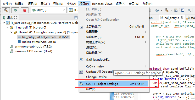
C++ 构建->设置->GNU ARM Cross C Linker->Miscellaneous去掉Other linker flags中的 “--specs=rdimon.specs”
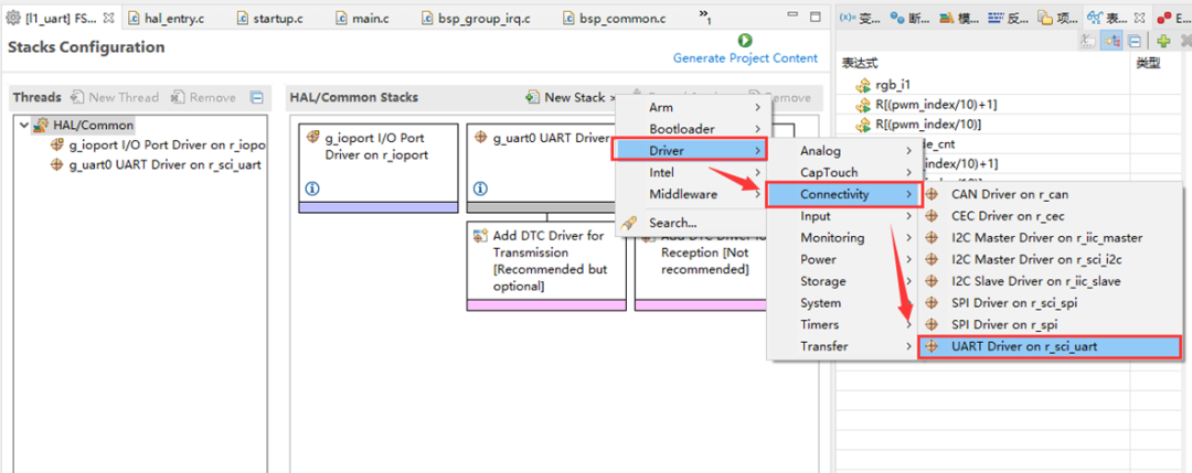
15.UART配置
点击Stacks->New Stack->Driver->Connectivity -> UART Driver on r_sci_uart。
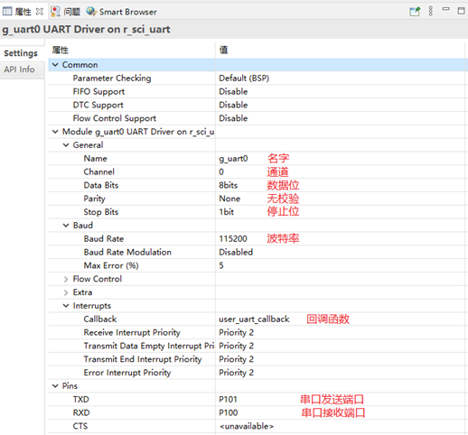
16.UART属性配置
配置串口,用于打印数据。
17.printf输出重定向到串口
打印最常用的方法是printf,所以要解决的问题是将printf的输出重定向到串口,然后通过串口将数据发送出去。
注意一定要加上头文件#include
#ifdef __GNUC__                                 //串口重定向
    #define PUTCHAR_PROTOTYPE int __io_putchar(int ch)
#else
    #define PUTCHAR_PROTOTYPE int fputc(int ch, FILE *f)
#endif

PUTCHAR_PROTOTYPE
{
        err = R_SCI_UART_Write(&g_uart0_ctrl, (uint8_t *)&ch, 1);
        if(FSP_SUCCESS != err) __BKPT();
        while(uart_send_complete_flag == false){}
        uart_send_complete_flag = false;
        return ch;
}
int _write(int fd,char *pBuffer,int size)
{
    for(int i=0;i;i++)>
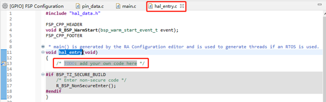
18.工厂文件
打开hal_entry.c,可以看到在hal_entry函数内,注释着可以在这输入自己的代码。
19.占空比与频率计算
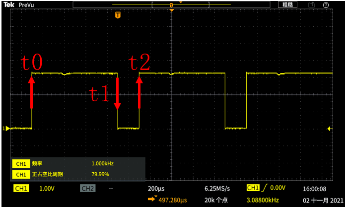
占空比=(t1-t0)/(t2-t0)
频率=(t2-t0)/时钟频率= =(t2-t0)/48M
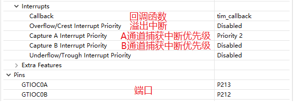
20.回调函数tim_callback()
由于设置了上升沿和下降沿都会进入回调函数中,故需要判断引脚电平来判断是属于高电平还是低电平。
bsp_io_level_t p_port_value_port_213;
/*读取端口电平状态,如果是低电平则发生的是下降沿,高电平则是上升沿*/
R_IOPORT_PinRead(&g_ioport_ctrl, BSP_IO_PORT_02_PIN_13, &p_port_value_port_213);
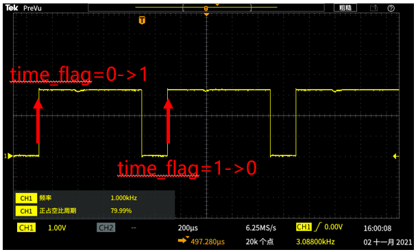
周期需要2个上升沿去判断,设定第一个上升沿time_flag由0变为1,则第二个上升沿则为time_flag由1变为0.
计算周期需要注意定时器周期计数器溢出,若存在time_flag= 0->1读取的计数值大于time_flag= 1->0读取的计数值,则一个周期为g_capture_num = current_period_counts + g_capture_num1 - g_capture_num0。
若没有溢出,则g_capture_num = g_capture_num1 - g_capture_num0。
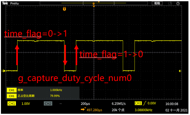
频率则需要计算下降沿到time_flag=1的一个周期,在除以g_capture_num(48M)。
计算频率需要注意定时器周期计数器溢出,若存在time_flag= 0->1读取的计数值大于g_capture_duty_cycle_num0读取的计数值,则一个周期为g_capture_num = current_period_counts + g_capture_num1 - g_capture_num0。若没有溢出,则g_capture_duty_cycle_num = g_capture_duty_cycle_num0 - g_capture_num0。
21.代码
#include "hal_data.h"
#include
FSP_CPP_HEADER
void R_BSP_WarmStart(bsp_warm_start_event_t event);
FSP_CPP_FOOTER
fsp_err_t err = FSP_SUCCESS;
volatile bool uart_send_complete_flag = false;//串口发送完毕标志位
volatile bool time_flag = 0;//上升沿标志位
volatile uint64_t g_capture_num =0;//两个上升沿之间的周期
volatile uint64_t g_capture_num0 =0;//第0个上升沿定时器计数值
volatile uint64_t g_capture_num1 =0;//第1个上升沿定时器计数值
volatile uint64_t g_capture_frequency = 0;//频率
volatile float g_capture_duty_cycle =0;//占空比
volatile int g_capture_duty_cycle_num =0;//+占空比周期
volatile uint64_t g_capture_duty_cycle_num0 =0;//下降沿定时器计数值
void user_uart_callback (uart_callback_args_t * p_args)
{
if(p_args->event == UART_EVENT_TX_COMPLETE)
{
uart_send_complete_flag = true;
}
}
#ifdef __GNUC__ //串口重定向
#define PUTCHAR_PROTOTYPE int __io_putchar(int ch)
#else
#define PUTCHAR_PROTOTYPE int fputc(int ch, FILE *f)
#endif
PUTCHAR_PROTOTYPE
{
err = R_SCI_UART_Write(&g_uart0_ctrl, (uint8_t *)&ch, 1);
if(FSP_SUCCESS != err) __BKPT();
while(uart_send_complete_flag == false){}
uart_send_complete_flag = false;
return ch;
}
int _write(int fd,char *pBuffer,int size)
{
for(int i=0;ievent) || (TIMER_EVENT_CAPTURE_B == p_args->event))
{
bsp_io_level_t p_port_value_port_213;
/*读取端口电平状态,如果是低电平则发生的是下降沿,高电平则是上升沿*/
R_IOPORT_PinRead(&g_ioport_ctrl, BSP_IO_PORT_02_PIN_13, &p_port_value_port_213);
/* Get the current period setting. */
timer_info_t info;
(void) R_GPT_InfoGet(&g_timer0_ctrl, &info);
uint64_t frequency = info.clock_frequency;//定时器时钟频率
uint32_t current_period_counts = info.period_counts;//定时器周期
if(p_port_value_port_213==BSP_IO_LEVEL_HIGH)//上升沿
{
if(time_flag==0)
{
time_flag=1;
g_capture_num0=p_args->capture;
g_capture_duty_cycle_num=0;
}
else
{
time_flag=0;
g_capture_num1=p_args->capture;
if(g_capture_num1>=g_capture_num0)
g_capture_num=g_capture_num1-g_capture_num0;
else
g_capture_num=current_period_counts+g_capture_num1-g_capture_num0;
g_capture_frequency= frequency/g_capture_num;//计算频率
}
}
else
{
if(time_flag==1)
{
g_capture_duty_cycle_num0=p_args->capture;
if(g_capture_duty_cycle_num0>=g_capture_num0)
g_capture_duty_cycle_num=g_capture_duty_cycle_num0-g_capture_num0;
else
g_capture_duty_cycle_num=current_period_counts+g_capture_duty_cycle_num0-g_capture_num0;
g_capture_duty_cycle=(g_capture_duty_cycle_num*100/(float)g_capture_num);//占空比
}
}
}
}
void hal_entry(void)
{
/* TODO: add your own code here */
err = R_SCI_UART_Open(&g_uart0_ctrl, &g_uart0_cfg);
assert(FSP_SUCCESS == err);
/* Initializes the module. */
err = R_GPT_Open(&g_timer0_ctrl, &g_timer0_cfg);
/* Handle any errors. This function should be defined by the user. */
assert(FSP_SUCCESS == err);
/* Start the timer. */
(void) R_GPT_Start(&g_timer0_ctrl);
/* Enable captures. Captured values arrive in the interrupt. */
(void) R_GPT_Enable(&g_timer0_ctrl);
/* Initializes the module. */
err = R_GPT_Open(&g_timer1_ctrl, &g_timer1_cfg);
/* Handle any errors. This function should be defined by the user. */
assert(FSP_SUCCESS == err);
R_BSP_SoftwareDelay (20, BSP_DELAY_UNITS_MILLISECONDS);
/* Start the timer. */
(void) R_GPT_Start(&g_timer1_ctrl);
R_BSP_SoftwareDelay (20, BSP_DELAY_UNITS_MILLISECONDS);
while(1)
{
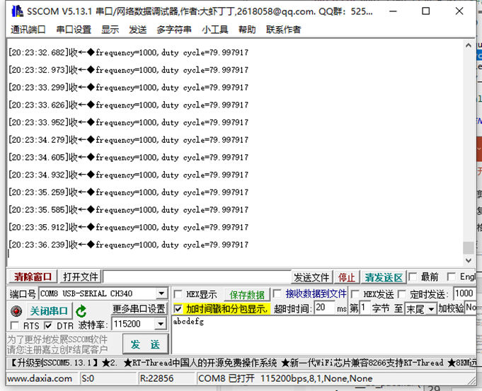
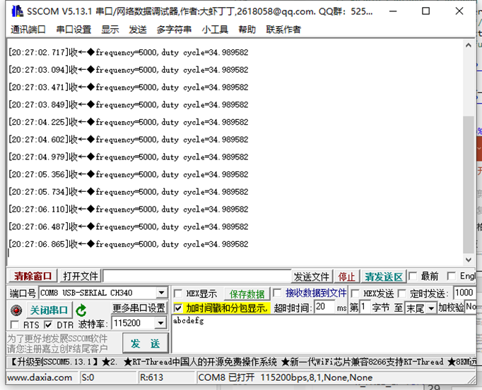
printf("\nfrequency=%lld,duty cycle=%f",g_capture_frequency,g_capture_duty_cycle);
g_capture_num=0;
g_capture_duty_cycle=0;
R_BSP_SoftwareDelay (200, BSP_DELAY_UNITS_MILLISECONDS);
}
#if BSP_TZ_SECURE_BUILD
/* Enter non-secure code */
R_BSP_NonSecureEnter();
#endif
} ;i++)>
22.结果演示
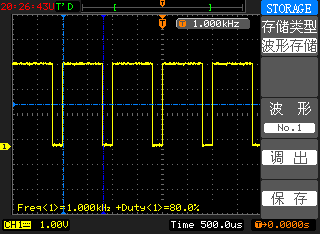
频率1K 占空比80%
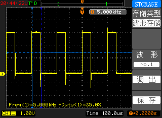
频率5K 占空比35%
23.视频教学
视频教学稍后会在B站官方账号更新,请留意B站视频更新~

原创:ByRA_Billy Xiao
原文标题:瑞萨e2studio----定时器GPT配置输入捕获
文章出处:【微信公众号:RA生态工作室】欢迎添加关注!文章转载请注明出处。
声明:本文内容及配图由入驻作者撰写或者入驻合作网站授权转载。文章观点仅代表作者本人,不代表电子发烧友网立场。文章及其配图仅供工程师学习之用,如有内容侵权或者其他违规问题,请联系本站处理。
举报投诉
-
mcu
+关注
关注
146文章
17073浏览量
350700 -
ARM
+关注
关注
134文章
9069浏览量
367158 -
嵌入式
+关注
关注
5081文章
19070浏览量
304290 -
开发板
+关注
关注
25文章
5001浏览量
97317
发布评论请先 登录
相关推荐

高级定时器PWM输入模式的配置方法
我们将向大家介绍高级定时器的另一个常见应用——PWM输入模式。在本节课中,我们将先围绕输入捕获模式展开,并重点描述PWM输入模式和涉及的寄存
瑞萨e2studio(1)----瑞萨芯片之搭建FSP环境
视频教学
样品申请
请勿添加外链
e2studio软件
e2studio是瑞萨的集成开发环境,FSP 提供了众多可提高效率的工具,用于开发针对瑞
发表于 09-30 15:28
瑞萨e2studio----SPI速率解析
在嵌入式系统的设计中,串行外设接口(SPI)的通信速率是一个关键参数,它直接影响到系统的性能和稳定性。瑞萨电子的RA4M2微控制器为开发者提供了灵活而强大的SPI

STM32的GPIO引脚能同时用作外部中断和定时器输入捕获吗?
今天突然在项目中想到一种用法,将GPIO的某一个引脚,同时配置外部中断(在中断中做一些逻辑)和复用为定时器的输入捕获引脚。
查看GPIO的原理框图,感觉可行。找个机会试试这种用法,于是
发表于 05-09 08:22
SEGGER与瑞萨电子合作,宣布集成开发工具Embedded Studio
SEGGER与Renesas Electronics(瑞萨电子)合作,宣布集成开发工具Embedded Studio现已集成到被称为Smart Configurator(智能配置

如果STM32定时器外接了正交编码器,该剩余通道是否能做PWM输出呢?
其实,对于STM32芯片,编码输入信号就是定时器的计数时钟源之一。定时器外接了编码输入,若还有剩余通道的话,剩余通道依然可以实现输入
使用TC21x的GPT实现1m计时器执行定时任务,怎么配置GTM和GPT?
专家们好,我想使用TC21x的GPT实现1m计时器执行定时任务,不知道怎么配置GTM和GPT?
发表于 02-06 06:47

GPT EVAL_BDPS_DRIVER可以使用GPT12 IP或GTM IP来实现连续定时器和单次定时器吗?
GPT EVAL_BDPS_DRIVER可以使用GPT12 IP或GTM IP来实现连续定时器和单次定时器? 是吗?
发表于 01-22 08:16
AT32 定时器配置中pr和div的作用
AT32定时器是51系列单片机中的一种定时器,可以实现多种定时功能。在AT32定时器中,pr和div是两个相关的参数,用于配置
一个通道如何捕获PWM的频率和占空比?
一,前言正常情况是双通道捕获PWM波,这种方法简单且准确,但是它占用的资源太多了,因为它使用定时器的两个通道,且这两个通道映射在一个通道上,同时配置一路捕获为触发


 工商网监
工商网监
评论