有时,由于波动,人们发现很难从interwetten与威廉的赔率体系 温度计读取温度。因此,在这里我们将使用8051微控制器构建一个简单的数字温度计,其中LM35传感器用于测量温度。我们还使用LM35构建使用Arduino,NodeMCU,PIC,Raspberry Pi和其他微控制器的数字温度计。
该项目还将作为ADC0804与8051和16*2 LCD与8051微控制器的适当接口。
所需组件:
8051开发板
ADC0804 板
16*2液晶显示屏
LM35 传感器
电位计
跳线
电路图:
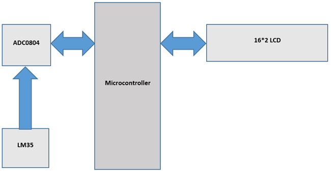
使用LM35的数字温度计电路的电路图如下:

使用 35 使用 8051 测量温度:
8051微控制器是一个8位微控制器,具有128字节的片上RAM,4K字节的片上ROM,两个定时器,一个串行端口和四个8位端口。8052微控制器是微控制器的扩展。下表显示了8051名家庭成员的比较。
| 特征 | 8051 | 8052 |
| 只读存储器(以字节为单位) | 4K | 8K |
| 内存(字节) | 128 | 256 |
| 定时器 | 2 | 3 |
| I/O 引脚 | 32 | 32 |
| 串行端口 | 1 | 1 |
| 中断源 | 6 | 8 |
16x2 液晶显示器:
16 * 2 LCD是嵌入式应用中广泛使用的显示器。以下是有关16 * 2液晶显示器的引脚和工作的简要说明。LCD内部有两个非常重要的寄存器。它们是数据寄存器和命令寄存器。命令寄存器用于发送清晰显示、光标在家乡等命令,数据寄存器用于发送要在16*2 LCD上显示的数据。下表显示了16 * 2 LCD的引脚说明。
| 针 | 象征 | I/O | 描述 |
| 1 | VSS | - | 地 |
| 2 | Vdd | - | +5V电源 |
| 3 | V形 | - | 用于控制对比度的电源 |
| 4 | RS | 我 |
RS=0 为命令寄存器 , RS=1 用于数据寄存器 |
| 5 | 乌尔曼 | 我 | R/W=0 表示写入,R/W=1 表示读取 |
| 6 | E | I/O | 使 |
| 7 | D0 | I/O | 8位数据总线 |
| 8 | D1 | I/O | 8位数据总线 |
| 9 | D2 | I/O | 8位数据总线 |
| 10 | D3 | I/O | 8位数据总线 |
| 11 | D4 | I/O | 8位数据总线 |
| 12 | D5 | I/O | 8位数据总线 |
| 13 | D6 | I/O | 8位数据总线 |
| 14 | D7 | I/O | 8位数据总线 |
| 15 | 一个 | - | +5V背光 |
| 16 | K | - | 地 |
下表显示了常用的液晶屏命令代码。
| 代码(十六进制) | 描述 |
| 01 | 清晰的显示屏 |
| 06 | 递增光标(右移) |
| 0安 | 显示关闭,光标打开 |
| 0C | 显示打开,光标关闭 |
| 0F | 显示于 ,光标闪烁 |
| 80 | 强制光标从 1 开始圣线 |
| C0 | 强制光标以 2 开头德·线 |
| 38 | 2行和5 * 7矩阵 |
ADC0804 集成电路:
ADC0804 IC是美国国家半导体公司ADC0800系列中的8位并行ADC。它的工作电压为+5伏,分辨率为8位。步长和 VIN 范围因 Vref/2 的不同值而异。下表显示了 Vref/2 和 VIN 范围之间的关系。
| Vref/2 (V) | 葡萄酒 (V) | 步长(mV) |
| 打开 | 0 到 5 | 19.53 |
| 2.0 | 0 到 4 | 15.62 |
| 1.5 | 0 到 3 | 11.71 |
| 1.28 | 0 到 2.56 | 10 |
在我们的例子中,Vref/2连接到1.28伏,因此步长为10mV。对于ADC0804,步长计算为(2 * Vref / 2)/256。
以下公式用于计算输出电压:
Dout = Vin / step size
其中Dout是以十进制输出的数字数据,Vin =模拟输入电压和步长(分辨率)是最小的变化。在此处了解有关ADC0804的更多信息,还可以检查ADC0808与8051的接口。
LM35 温度传感器:
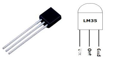
LM35 是一款温度传感器,其输出电压与摄氏温度成线性比例。LM35 已经校准,因此不需要外部校准。它每摄氏度温度输出 10mV。
LM35 传感器产生与温度相对应的电压。该电压由ADC0804转换为数字(0至256),并馈送到8051微控制器。8051微控制器将此数字值转换为以摄氏度为单位的温度。然后将该温度转换为适合显示的ascii形式。此 ascii 值被馈送到 16*2 LCD,该 LCD 在其屏幕上显示温度。此过程在指定的时间间隔后重复。
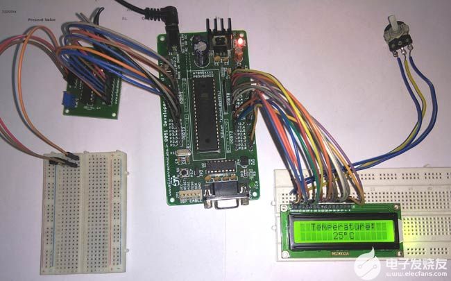
以下是使用 8051 的 LM35 数字温度计的设置映像:
您可以在此处找到所有基于 LM35 的数字温度计。
代码说明:
使用LM35的数字温度计的完整C程序在本项目结束时给出。代码被分成有意义的小块,并在下面解释。
对于 16*2 LCD 与 8051 微控制器接口 ,我们必须定义 16*2 LCD 连接到 8051 微控制器的引脚。16*2 LCD 的 RS 引脚连接到 P2.7,16*2 LCD 的 RW 引脚连接到 P2.6,16*2 LCD 的 E 引脚连接到 P2.5。数据引脚连接到 8051 微控制器的端口 0。
sbit rs=P2^7; //Register Select(RS) pin of 16*2 lcd
sbit rw=P2^6; //Read/Write(RW) pin of 16*2 lcd
sbit en=P2^5; //Enable(E) pin of 16*2 lcd
同样,对于ADC0804与8051微控制器的接口,我们必须定义ADC0804连接到8051微控制器的引脚。ADC0804的RD引脚连接到P3.0,ADC0804的WR引脚连接到P3.1,ADC0804的INTR引脚连接到P3.2。数据引脚连接到 8051 微控制器的端口 1。
sbit rd_adc=P3^0; //Read(RD) pin of ADC0804
sbit wr_adc=P3^1; //Write(WR) pin of ADC0804
sbit intr_adc=P3^2; //Interrupt(INTR) pin of ADC0804
接下来,我们必须定义一些在程序中使用的函数。延时功能用于创建指定的时间延迟,c mdwrt功能用于向16 * 2 LCD显示器发送命令,datawrt功能用于将数据发送到16 * 2 LCD显示器,convert_display功能用于将ADC数据转换为温度并将其显示在16 * 2 LCD显示器上。
void delay(unsigned int) ; //function for creating delay
void cmdwrt(unsigned char); //function for sending commands to 16*2 lcd display
void datawrt(unsigned char); //function for sending data to 16*2 lcd display
void convert_display(unsigned char); //function for converting ADC value to temperature and display it on 16*2 lcd display
在下面的代码部分中,我们将命令发送到 16*2 lcd。清除显示、递增光标、强制光标以 1 开头等命令圣在指定的时间延迟后,线被一一发送到16 * 2液晶显示器。
for(i=0;i<5;i++) //send commands to 16*2 lcd display one command at a time
{
cmdwrt(cmd[i]); //function call to send commands to 16*2 lcd display
delay(1);
}
在代码的这一部分中,我们将数据发送到 16*2 lcd。要在16 * 2 LCD显示屏上显示的数据在指定的时间延迟后被逐个发送以显示。
for(i=0;i<12;i++) //send data to 16*2 lcd display one character at a time
{
datawrt(data1[i]); //function call to send data to 16*2 lcd display
delay(1);
}
在代码的这一部分中,我们将LM35传感器产生的模拟电压转换为数字数据,然后将其转换为温度并显示在16 * 2 LCD显示屏上。为了使ADC0804开始转换,我们必须在ADC0804的WR引脚上发送低到高脉冲,然后我们必须等待转换结束。INTR 在转换结束时变低。一旦INTR变为低电平,RD就会变为低电平,以将数字数据复制到8051微控制器的端口0。在指定的时间延迟后,下一个周期开始。这个过程将永远重复。
while(1) //repeat forever
{
wr_adc=0; //send LOW to HIGH pulse on WR pin
delay(1);
wr_adc=1;
while(intr_adc==1); //wait for End of Conversion
rd_adc=0; //make RD = 0 to read the data from ADC0804
value=P1; //copy ADC data
convert_display(value); //function call to convert ADC data into temperature and display it on 16*2 lcd display
delay(1000); //interval between every cycles
rd_adc=1; //make RD = 1 for the next cycle
}
在下面的部分代码中,我们将命令发送到 16*2 LCD 显示器。该命令将复制到 8051 微控制器的端口 0。对于命令写入,RS 设置为低电平。对于写入操作,RW 设置为低电平。在使能(E)引脚上施加高到低脉冲以启动命令写入操作。
void cmdwrt (unsigned char x)
{
P0=x; //send the command to Port 0 on which 16*2 lcd is connected
rs=0; //make RS = 0 for command
rw=0; //make RW = 0 for write operation
en=1; //send a HIGH to LOW pulse on Enable(E) pin to start commandwrite operation
delay(1);
en=0;
}
在代码的这一部分中,我们将数据发送到16 * 2 LCD显示器。数据将复制到 8051 微控制器的端口 0。RS 设置为高,用于命令写入。对于写入操作,RW 设置为低电平。在使能(E)引脚上施加高到低脉冲以启动数据写入操作。
void datawrt (unsigned char y)
{
P0=y; //send the data to Port 0 on which 16*2 lcd is connected
rs=1; //make RS = 1 for command
rw=0; //make RW = 0 for write operation
en=1; //send a HIGH to LOW pulse on Enable(E) pin to start datawrite operation
delay(1);
en=0;
}
在代码的这一部分中,我们将数字数据转换为温度并将其显示在16 * 2 LCD显示屏上。
void convert_display(unsigned char value)
{
unsigned char x1,x2,x3;
cmdwrt(0xc6); //command to set the cursor to 6th position of 2nd line on 16*2 lcd
x1=(value/10); //divide the value by 10 and store quotient in variable x1
x1=x1+(0x30); //convert variable x1 to ascii by adding 0x30
x2=value%10; //divide the value by 10 and store remainder in variable x2
x2=x2+(0x30); //convert variable x2 to ascii by adding 0x30
x3=0xDF; //ascii value of degree(°) symbol
datawrt(x1); //display temperature on 16*2 lcd display
datawrt(x2);
datawrt(x3);
datawrt('C');
}
完整代码:
/*this program is for displaying the temperature on 16*2 lcd display using 8051 microcontroller , LM35 sensor and ADC0804*/
#include
sbit rs=P2^7; //Register Select(RS) pin of 16*2 lcd
sbit rw=P2^6; //Read/Write(RW) pin of 16*2 lcd
sbit en=P2^5; //Enable(E) pin of 16*2 lcd
sbit rd_adc=P3^0; //Read(RD) pin of ADC0804
sbit wr_adc=P3^1; //Write(WR) pin of ADC0804
sbit intr_adc=P3^2; //Interrupt(INTR) pin of ADC0804
void delay(unsigned int) ; //function for creating delay
void cmdwrt(unsigned char); //function for sending commands to 16*2 lcd display
void datawrt(unsigned char); //function for sending data to 16*2 lcd display
void convert_display(unsigned char); //function for converting ADC value to temperature and display it on 16*2 lcd display
void main(void) //main function
{
unsigned char i;
unsigned char cmd[]={0x38,0x01,0x06,0x0c,0x82};//16*2 lcd initialization commands
unsigned char data1[]="Temperature:";
unsigned char value;
P1=0xFF; //make Port 1 as input port
P0=0x00; //make Port 0 as output port
for(i=0;i<5;i++) //send commands to 16*2 lcd display one command at a time
{
cmdwrt(cmd[i]); //function call to send commands to 16*2 lcd display
delay(1);
}
for(i=0;i<12;i++) //send data to 16*2 lcd display one character at a time
{
datawrt(data1[i]); //function call to send data to 16*2 lcd display
delay(1);
}
intr_adc=1; //make INTR pin as input
rd_adc=1; //set RD pin HIGH
wr_adc=1; //set WR pin LOW
while(1) //repeat forever
{
wr_adc=0; //send LOW to HIGH pulse on WR pin
delay(1);
wr_adc=1;
while(intr_adc==1); //wait for End of Conversion
rd_adc=0; //make RD = 0 to read the data from ADC0804
value=P1; //copy ADC data
convert_display(value); //function call to convert ADC data into temperature and display it on 16*2 lcd display
delay(1000); //interval between every cycles
rd_adc=1; //make RD = 1 for the next cycle
}
}
void cmdwrt (unsigned char x)
{
P0=x; //send the command to Port 0 on which 16*2 lcd is connected
rs=0; //make RS = 0 for command
rw=0; //make RW = 0 for write operation
en=1; //send a HIGH to LOW pulse on Enable(E) pin to start commandwrite operation
delay(1);
en=0;
}
void datawrt (unsigned char y)
{
P0=y; //send the data to Port 0 on which 16*2 lcd is connected
rs=1; //make RS = 1 for command
rw=0; //make RW = 0 for write operation
en=1; //send a HIGH to LOW pulse on Enable(E) pin to start datawrite operation
delay(1);
en=0;
}
void convert_display(unsigned char value)
{
unsigned char x1,x2,x3;
cmdwrt(0xc6); //command to set the cursor to 6th position of 2nd line on 16*2 lcd
x1=(value/10); //divide the value by 10 and store quotient in variable x1
x1=x1+(0x30); //convert variable x1 to ascii by adding 0x30
x2=value%10; //divide the value by 10 and store remainder in variable x2
x2=x2+(0x30); //convert variable x2 to ascii by adding 0x30
x3=0xDF; //ascii value of degree(°) symbol
datawrt(x1); //display temperature on 16*2 lcd display
datawrt(x2);
datawrt(x3);
datawrt('C');
}
void delay(unsigned int z)
{
unsigned int p,q;
for(p=0;p
{
for(q=0;q<1375;q++); //repeat for 1375 times
}
}
-
微控制器
+关注
关注
48文章
7555浏览量
151436 -
8051
+关注
关注
3文章
310浏览量
51502 -
数字温度计
+关注
关注
3文章
108浏览量
21728
发布评论请先 登录
相关推荐
如何使用8051微控制器和蓝牙模块构建一个Android手机控制的机器人


 如何使用8051微控制器构建一个简单的数字温度计


评论