RT_Tread studio提供spi外设简单的配置,使得从其他项目移置LCD变得非常简单,这一次记录如何从stm32 spi 驱动st77355移植到N32G457XVL-STB开发板上。
找到ST7735的示例
我原先在51黑论坛找到的例子:
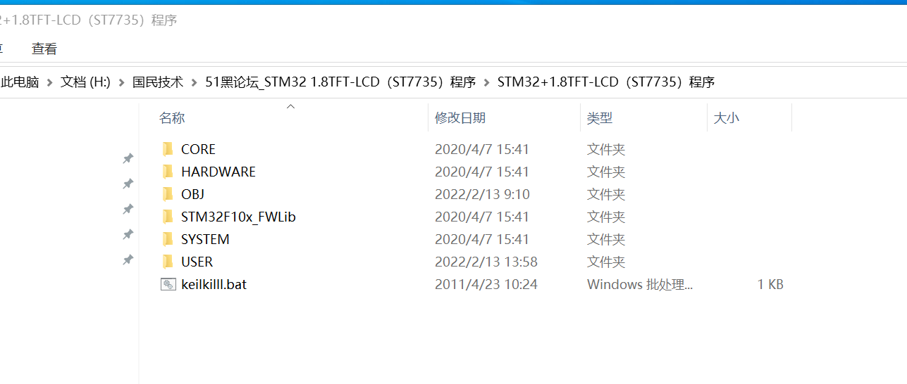
他是一个用stm32库函数实现的驱动LCD—ST7735的例子,在其工程目录下面有一个LCD的文件夹,我们今天就用这文件来移植实验:
其目录如下:
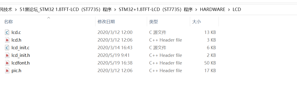
lcd.c/h 主要的功能是实现st7735画点、画线、画字等功能函数
lcd_init.c/h 主要实现的硬件接入函数,我们今天的主要改造就对这个函数进行改造移植。
lcdfont.h、pic.h主要是字库函数,不需要改造,直接可以用。
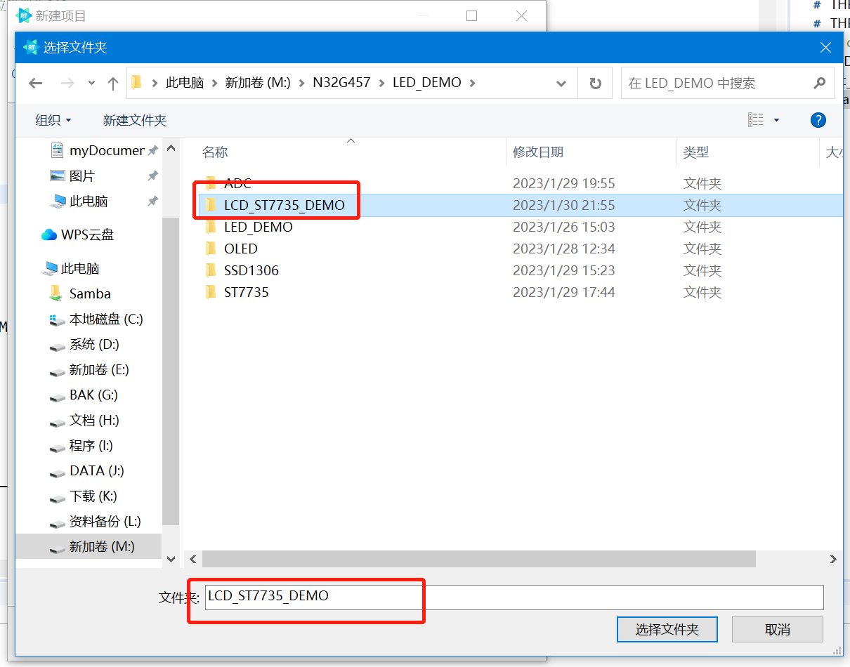
新建LCD_ST7735工程
1、打开RT-Thread Studio,并新建空的工程:(这样新建不细说,详细的新建工程见我上篇帖子:【国民威廉希尔官方网站
N32项目移植】N32G457项目移植之RT-Thread OLED
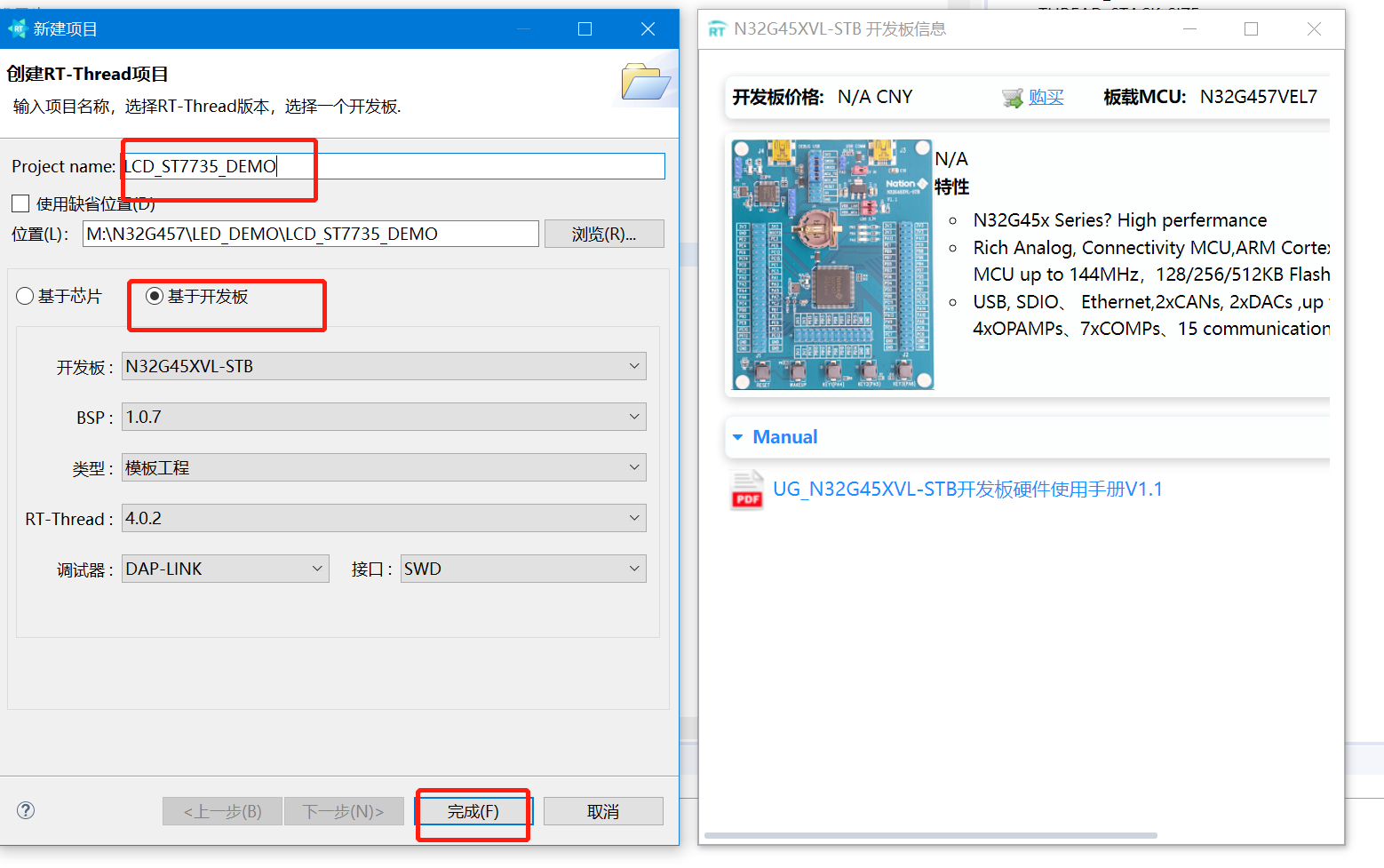
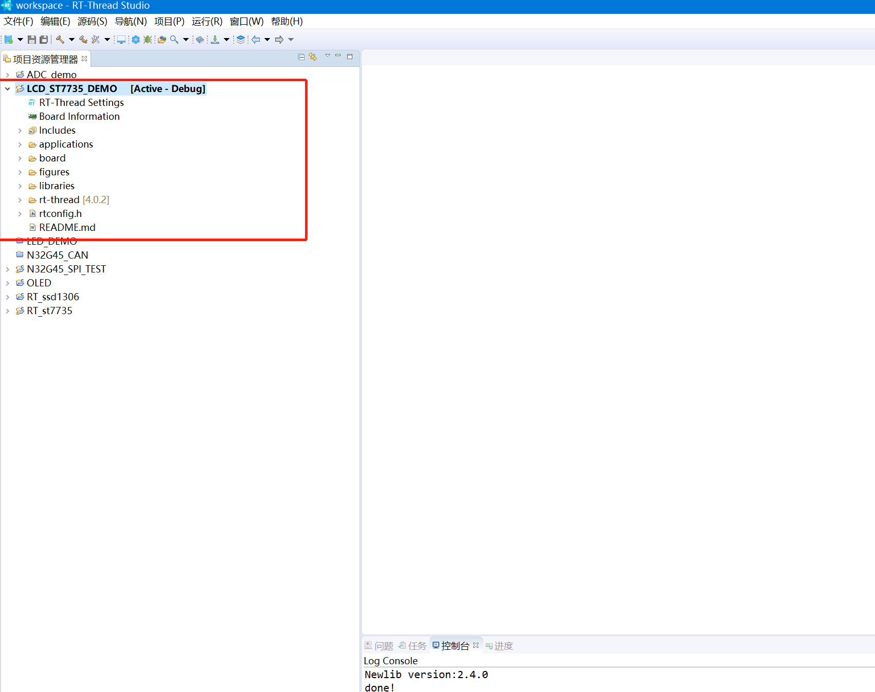
最后生成工程如下:
打开spi配置
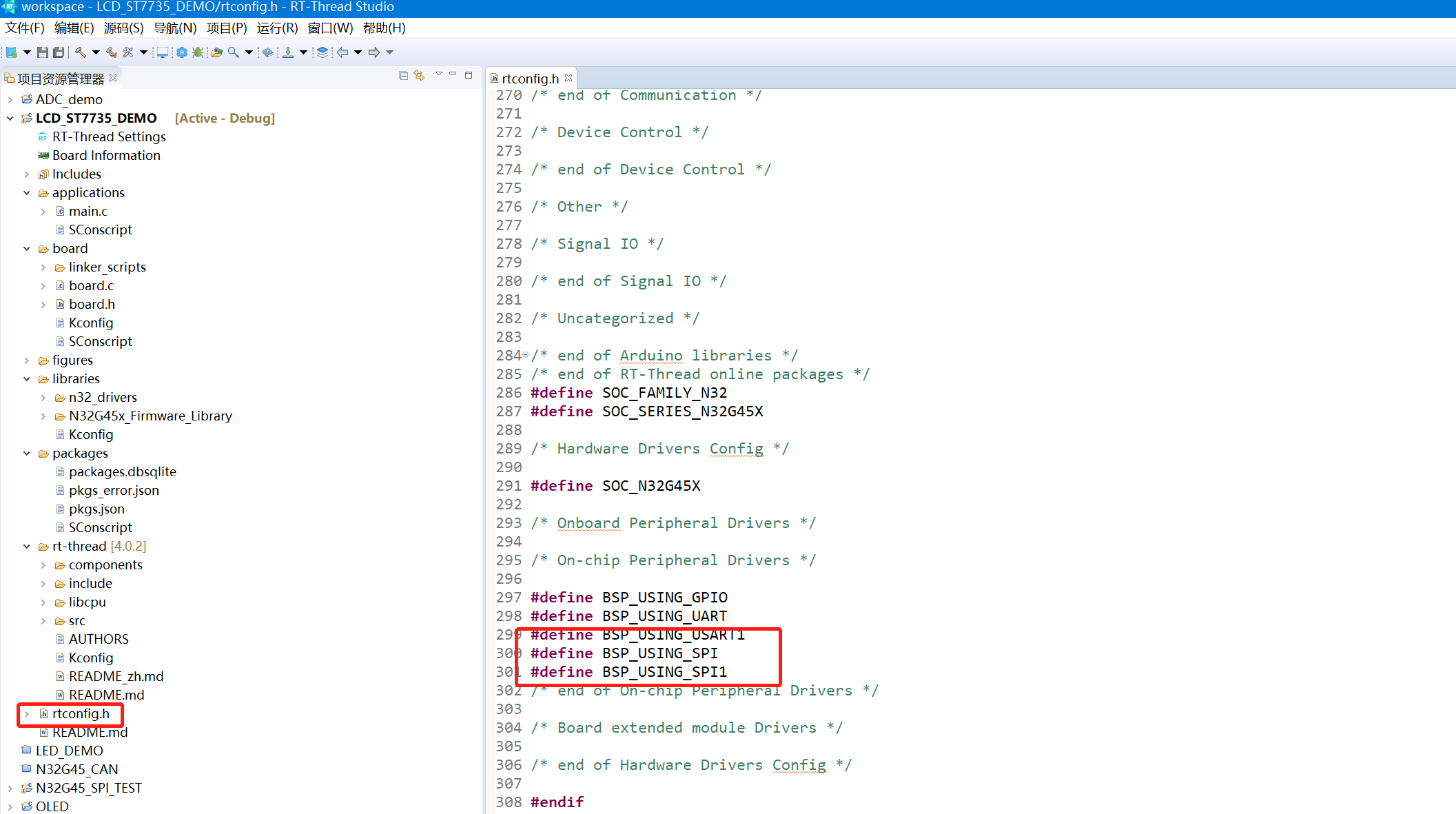
1、进入RT-Thread Settings 打开spi1配置
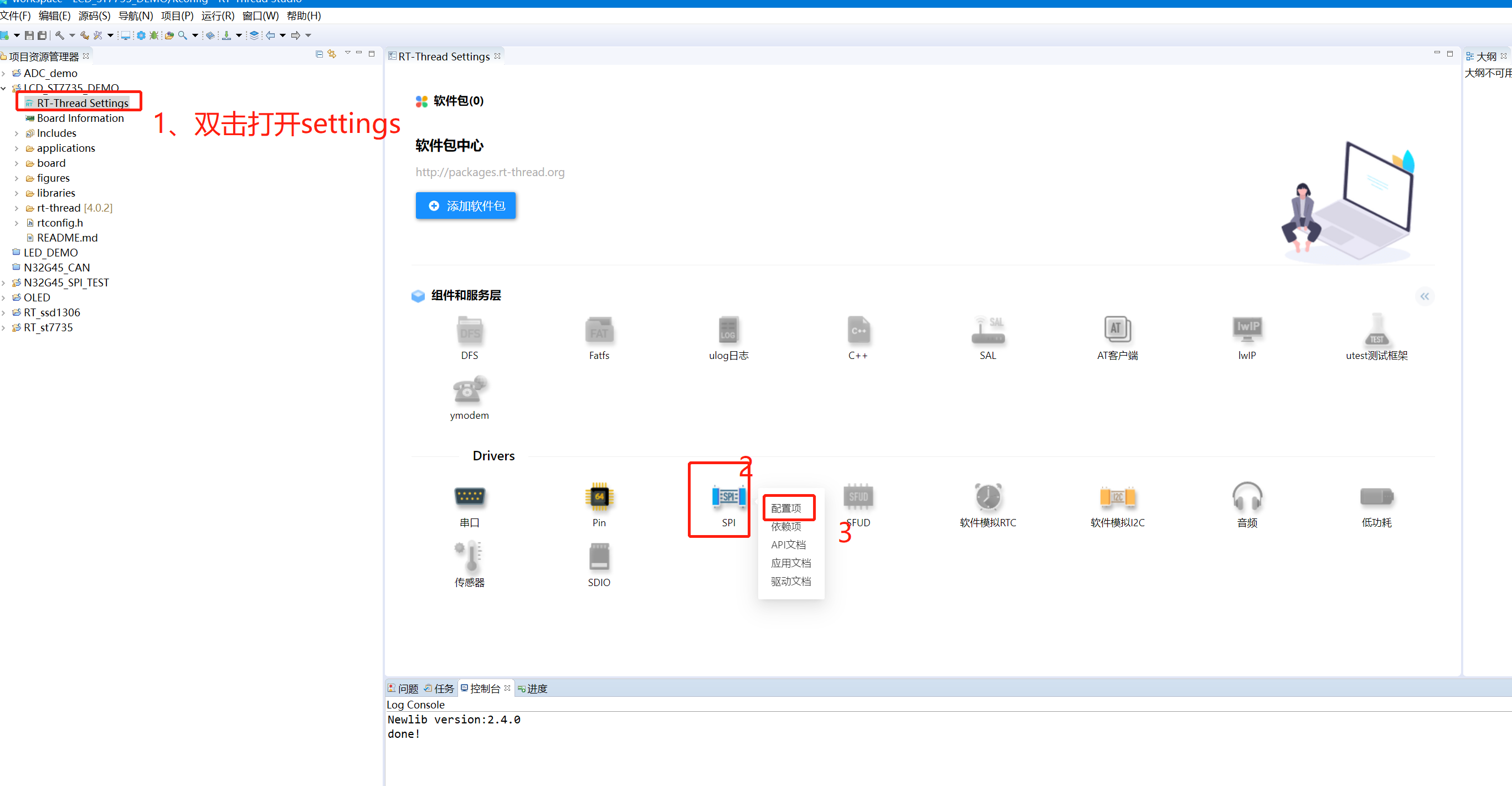
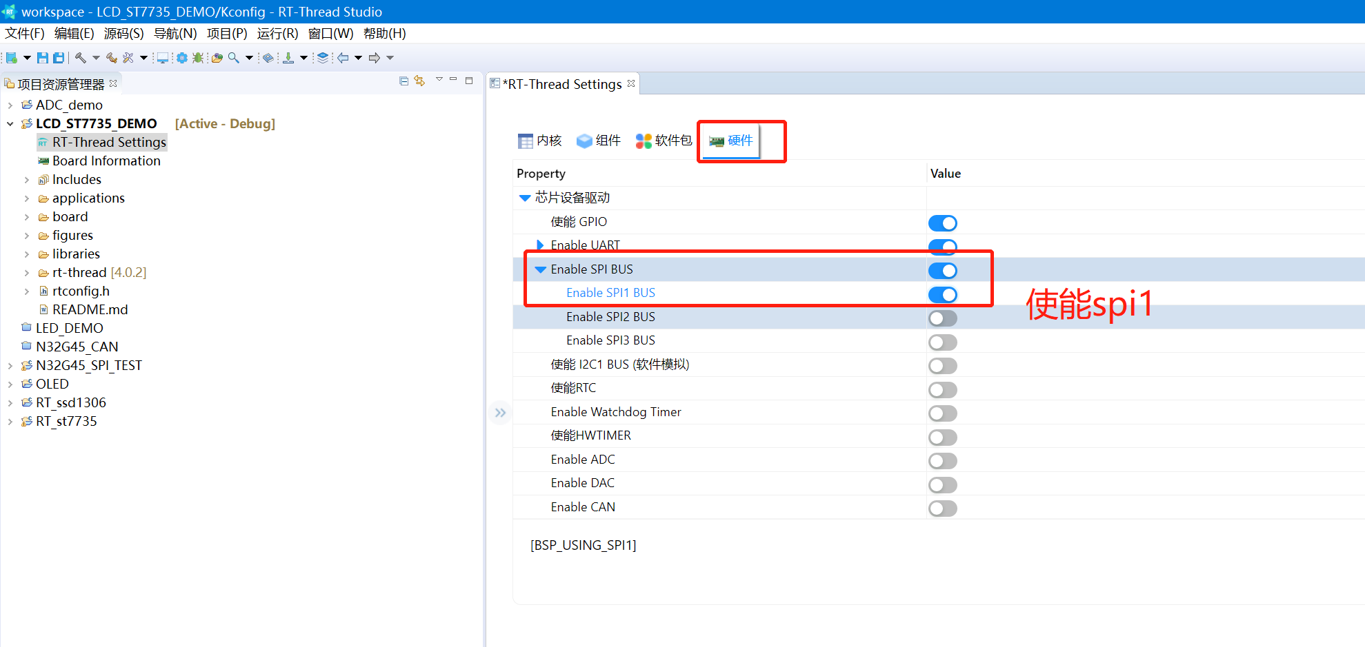
2、找到硬件,打开spi1
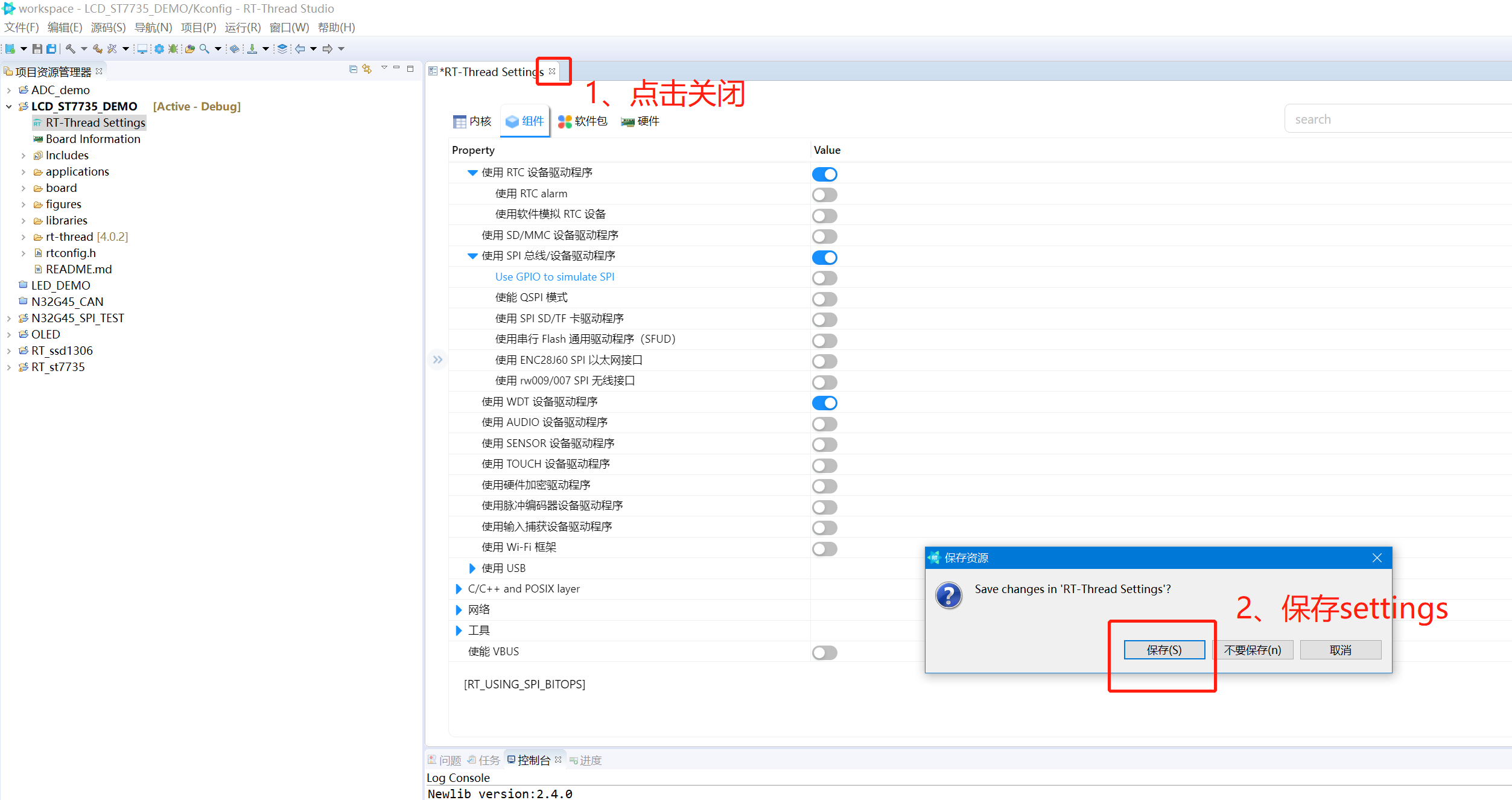
3、关闭settings 保存配置:
4、我们看到rtconfig.h配置了SPI1:
定义IO引脚
我们这里次选用SPI1 以及对印的IO如下:
/***************************************************************************
//  作    者   : 刘建华
//  生成日期   : 2023-1-30
//  最近修改   :
//  功能描述   :N32G45 st7735
//              说明:
//              ----------------------------------------------------------------
//              GND   电源地
//              VCC   3.3v电源
#define RES_PIN  36  //PC4   33
#define DC_PIN   37  //PC5   34
#define BLK_PIN  16  //PB0   35
#define SCK_PIN  5  //PA5
#define MOSI_PIN 7  //PA7
#define CS_PIN   4  //PA4
//              ----------------------------------------------------------------
对应lcd_init.h加入对PIN、以及相应的spi的定义:
#define RES_PIN 36
#define DC_PIN 37
#define BLK_PIN 16
#define SCK_PIN 5
#define MOSI_PIN 7
#define CS_PIN 4
#define SPIy SPI1
#define SPIy_CLK RCC_APB2_PERIPH_SPI1
#define SPIy_GPIO GPIOA
#define SPIy_GPIO_CLK RCC_APB2_PERIPH_GPIOA
#define SPIy_PIN_SCK GPIO_PIN_5
#define SPIy_PIN_MISO GPIO_PIN_6
#define SPIy_PIN_MOSI GPIO_PIN_7
#define SYSCLK_PLLHSI_FREQ_24MHz
#define LCD_SCLK_Clr() rt_pin_write(SCK_PIN, PIN_LOW)
#define LCD_SCLK_Set() rt_pin_write(SCK_PIN, PIN_HIGH)
#define LCD_MOSI_Clr() rt_pin_write(MOSI_PIN, PIN_LOW)
#define LCD_MOSI_Set() rt_pin_write(MOSI_PIN, PIN_HIGH)
#define LCD_CS_Clr() rt_pin_write(CS_PIN, PIN_LOW)
#define LCD_CS_Set() rt_pin_write(CS_PIN, PIN_HIGH)
#define LCD_RES_Clr() rt_pin_write(RES_PIN, PIN_LOW)
#define LCD_RES_Set() rt_pin_write(RES_PIN, PIN_HIGH)
#define LCD_DC_Clr() rt_pin_write(DC_PIN, PIN_LOW)
#define LCD_DC_Set() rt_pin_write(DC_PIN, PIN_HIGH)
#define LCD_BLK_Clr() rt_pin_write(BLK_PIN, PIN_LOW)
#define LCD_BLK_Set() rt_pin_write(BLK_PIN, PIN_HIGH)
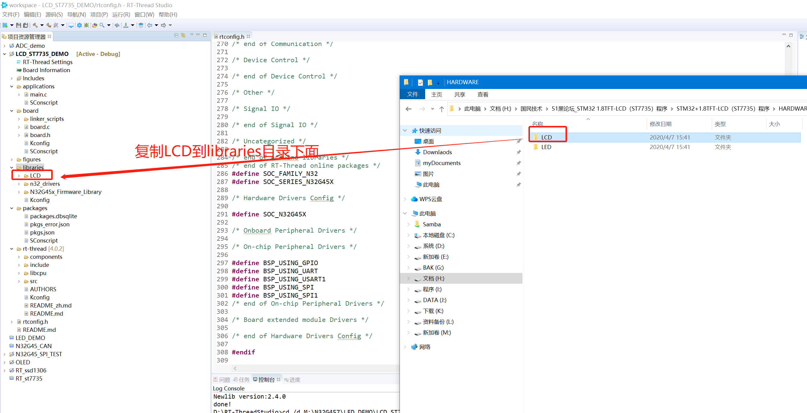
移植lcd文件夹到项目里:
1、从stm32项目复制LCD到libraries目录下面:
2、打开lcd_init.c,引入头rt-thread文件:
#include <rtthread.h>
#include <rtdevice.h>
#include <stdint.h>
#include <n32g45x.h>
#include "drv_gpio.h"
#include "rtconfig.h"
3、添加定义spi1 usb的名称
#define SPI1_BUS_NAME         "spi1"
#define SPI1__DEVICE_NAME     "spi10"
4、定义n32_hw_spi_cs 片选的结构体定义:
struct n32_hw_spi_cs
{
    GPIO_Module* GPIOx;
    uint32_t GPIO_Pin;
};
5、实例化st7735的设备
struct rt_spi_device *st7753_spi_dev;
6、配置st7735 spi设备,并且在开机时注册设备:
int rt_hw_spi_config(void)
{
    static struct n32_hw_spi_cs  spi_cs1;
    static struct rt_spi_device spi_dev_1 ;
    rt_err_t res;
    spi_cs1.GPIO_Pin = CS_PIN;
    spi_cs1.GPIOx = GPIOA;
    rt_pin_mode(CS_PIN, PIN_MODE_OUTPUT);
    res = rt_spi_bus_attach_device(&spi_dev_1, SPI1__DEVICE_NAME, SPI1_BUS_NAME, (void*)&spi_cs1);
    if (res != RT_EOK)
    {
        rt_kprintf("rt_spi_bus_attach_device!\r\n");
        return res;
    }
    spi_dev_1.bus->owner = &spi_dev_1;
    {
        struct rt_spi_configuration cfg;
        cfg.data_width = 8;
        cfg.mode =   RT_SPI_MODE_3 | RT_SPI_MSB ;
        cfg.max_hz = 40*1000 *1000; /* 40M,SPI max 42MHz, 3-wire spi */
        if(spi_dev_1.bus->owner==RT_NULL)
        {
            rt_kprintf("RT_OK\r\n");
        }
        rt_kprintf("owner= %d\r\n",*spi_dev_1.bus->owner);
        res = rt_spi_configure(&spi_dev_1, &(cfg));
        if(res != RT_EOK)
        {
            rt_kprintf("configure spi1 ERR!\r\n");
        }

    }
    st7753_spi_dev = (struct rt_spi_device *)rt_device_find(SPI1__DEVICE_NAME);
        if(!&st7753_spi_dev)
        {
            rt_kprintf("spi1 test run failed! can't find %s device!\n", SPI1__DEVICE_NAME);
        }
    return RT_EOK;
}

INIT_DEVICE_EXPORT(rt_hw_spi_config);
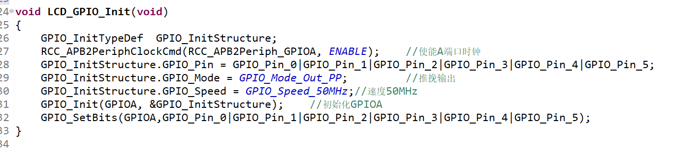
8、 开始修改LCD_GPIO_Init函数
原来的GPIO_LCD_Init函数主要是配spi SCK、MOSI、MISO、以及DC、CS、REST的GPIO初始化,我们这里只需要对DC、CS、REST、BL进行初始化就行了。
将原型:
修改为:
void LCD_GPIO_Init(void)
{
rt_pin_mode(RES_PIN, PIN_MODE_OUTPUT);
rt_pin_mode(DC_PIN, PIN_MODE_OUTPUT);
rt_pin_mode(BLK_PIN, PIN_MODE_OUTPUT);
rt_pin_mode(CS_PIN, PIN_MODE_OUTPUT);
}
9、修改LCD_Writ_Bus函数:
原来的函数:
/******************************************************************************
      函数说明:LCD串行数据写入函数
      入口数据:dat  要写入的串行数据
      返回值:  无
******************************************************************************/
void LCD_Writ_Bus(u8 dat)
{
	u8 i;
	LCD_CS_Clr();
	for(i=0;i<8;i++)
	{
		LCD_SCLK_Clr();
		if(dat&0x80)
		{
		   LCD_MOSI_Set();
		}
		else
		{
		   LCD_MOSI_Clr();
		}
		LCD_SCLK_Set();
		dat<<=1;
	}
  LCD_CS_Set();
}
修改为:
void LCD_Writ_Bus(uint8_t dat)
{
    rt_spi_send(st7753_spi_dev, &dat, 1);
}
看起来简单多了吧。。。
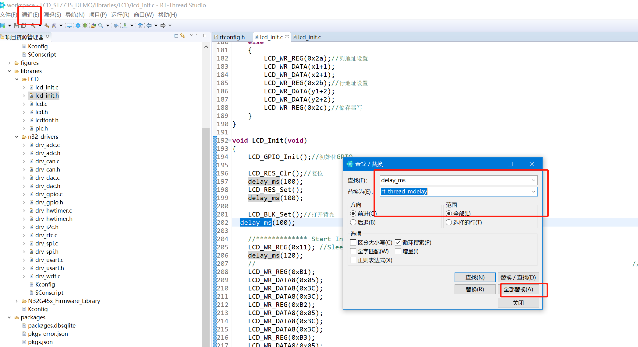
10、把原来的delay_ms修改的rttread的rt_thread_mdelay
直接打开菜单: 编译->查找/替换菜单中,把delay_ms替换为rt_thread_mdelay就行:
11、把原来的u8、u16 、u32全部替换回uint8_t 、uint16_t、uint32_t或者typedef一下就行
到这里函数的修改就完成了。
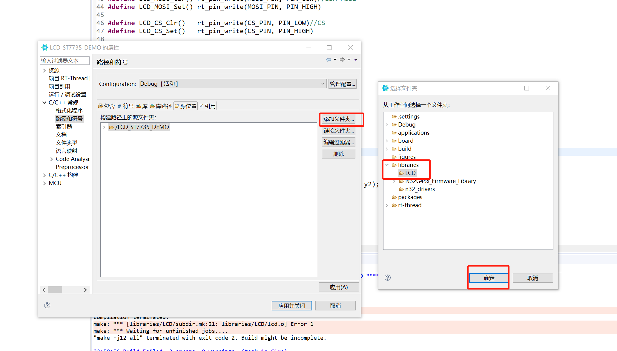
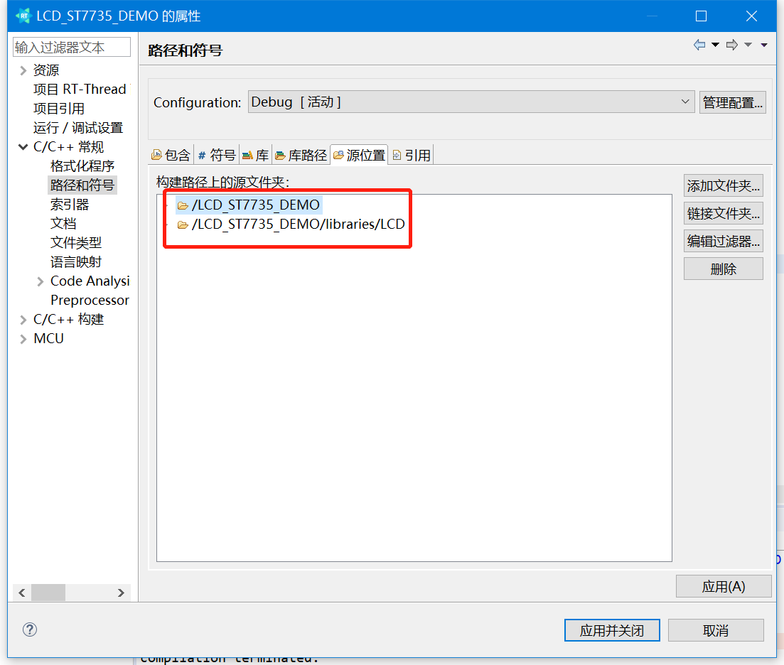
添加头文件路径、包含目录
在工程名称上右键,选择属性——>C/C++常规——>源位置:

选择添加文件,选择libraries下的LCD文件夹,然后确定,应用并关闭
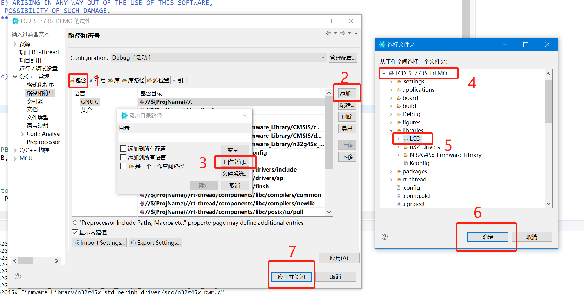
2、按下图所示,添加包含LCD的路径:
主函数下面添加demo显示
1、main.c添加lcd.h的头文件引用。
#include "lcd_init.h"
#include "lcd.h"
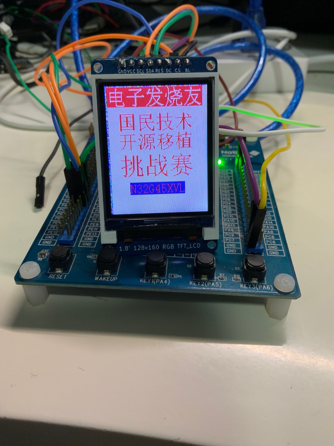
2、在main主函数添加显示函数如下:
    LCD_Init();//LCD初始化
    LCD_Fill(0,0,LCD_W,LCD_H,WHITE);
    LCD_ShowChinese(0,0,"电子发烧友",WHITE,RED,24,0);
    LCD_ShowChinese(12,30,"国民威廉希尔官方网站
",RED,WHITE,24,1);
    LCD_ShowChinese(12,30+24,"开源移植",RED,WHITE,24,1);
    LCD_ShowChinese(12,80,"挑战赛",RED,WHITE,32,1);
    LCD_ShowString(24,118,"N32G45XVL",RED,BLUE,16,0);
编译下载:
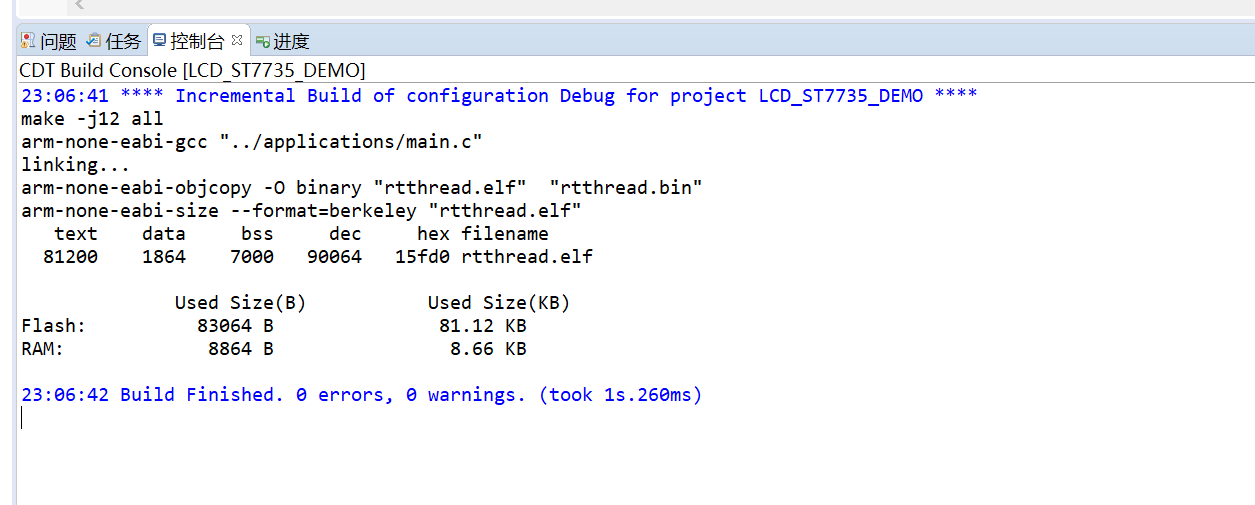
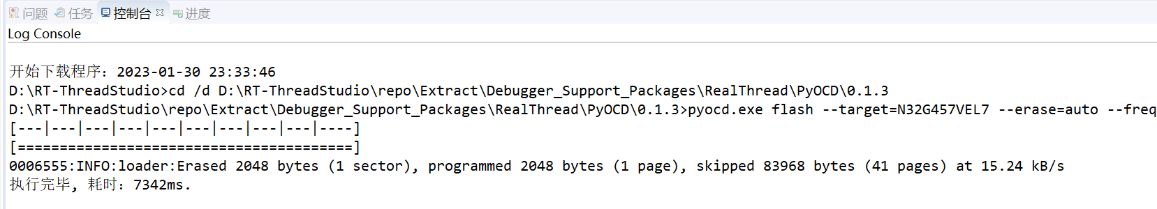
移植效果:
附工程文件:
*附件:LCD_ST7735_DEMO.zip
【小结】这次移植spi _ST7735的项目,减少了繁琐的spi配置,如果是移植到其芯片的rtthread工程,那将更将简单。所以说上RTT_Thread 会让你的工作事半功倍。
 /6
/6 


 工商网监
湘ICP备2023018690号
工商网监
湘ICP备2023018690号


 1857
1857


 淘帖
淘帖 显身卡
显身卡


